Friday, August 30, 2013
Simple Tiny Door Guard
This simple Door Chime protects the door and gives a loud Alarm tone when there is an attempt of theft. The circuit is too simple and battery operated. A Normally Closed (NC) reed switch and magnet is used to trigger the circuit. Alarm generator is the popular ROM IC UM 3561. This 8 pin IC has an inbuilt oscillator to generate 4 siren tones like, Ambulance siren, Police siren, Fire brigade siren and Gun sound. The different tones can be selected using its pin 6 connected to VCC, Ground or not connected. Frequency of oscillation is determined by the 220K resistor connected to the pins 7 and 8 of the IC.UM 3561 is the low power IC and its maximum voltage rating is 3 volts. So Zener diode ZD is used to give 3 volts supply to IC. Medium power NPN transistor T1 amplifies the output pulses from IC1 to a loud siren.
Tiny Door Guard Circuit diagram:
Magnet can be a small sized one that is to be fixed in the door using double sided adhesive tape. Fix the circuit board in the door frame. Fix Reed switch in the door frame, very close to the door. So that, when the door is closed, the magnet will pull the contacts of the reed switch to break supply to the IC. When the door opens, contacts of the reed switch make contact and IC gets power to give alarm.
Tiny Door Guard Circuit diagram:

Magnet can be a small sized one that is to be fixed in the door using double sided adhesive tape. Fix the circuit board in the door frame. Fix Reed switch in the door frame, very close to the door. So that, when the door is closed, the magnet will pull the contacts of the reed switch to break supply to the IC. When the door opens, contacts of the reed switch make contact and IC gets power to give alarm.
Thursday, August 15, 2013
High Voltage Regulator Circuit Diagram
The High Voltage Regulator Circuit Diagram delivers 100-V at 100 mA and withstands shorts to ground. Even at 100 V output, the LT317A functions in the normal mode, maintaining 1.2 V between its output and adjustment pin. Under these conditions, the 30-V zener is off and Ql conducts. When an output short occurs, the zener conducts, forcing Q1`s base to 30 V.
This causes Q1`s emitter to clamp 2 VnEs below Vz. well within the V.w VouT rating of the regulator. Under these conditions, Q1, a high-voltage device, sustains 90 V-VcE at whatever current the transformer specified saturates at 130 mA, while Q1 safely dissipates 12 W. If Q1 and the LT317 A are thermally coupled, the regulator will soon go into thermal shutdown and oscillation will commence.
This action will continue, protecting the load and the regulator as long as the output remains shorted. The 500-pF capacitor and the 10 0/0.02 11F damper aid transient response and the diodes provide safe discharge paths for the capacitors.
High Voltage Regulator Circuit Diagram

Wednesday, August 14, 2013
Safety Isolating Transformer
1. Introduction
The purpose of this module is to set safety standards for safety isolating transformers in technical areas and workshops.
The purpose of this module is to set safety standards for safety isolating transformers in technical areas and workshops.
This guidance does not apply to auto-transformers (which should not be used), transformers used on building sites (110V or 50-0-50V) nor to isolating transformers used in vehicles e.g. OB Scanners and satellite trucks.
The safety isolating transformers covered by this Guidance Note will be various types and will be found:
• as free standing units in workshops
• built in to workshop bench supplies and marked as ‘isolated supply’
• in Radio and TV Studios
• in use with Performers’ equipment in studios
1.1. Safety Isolating Transformers - Principles of operation
A safety isolating transformer is where the input voltage and output voltage are identical, rather than at Separated Extra-Low Voltage (SELV 50V rms maximum), which is strictly the definition in BS 3535. Additionally BS 3535 would exclude the use of domestic socket outlets on the output.
The primary and secondary windings are isolated to Class ll standards by either an earthed electrolytic screen or by being constructed with separate windings on the core. This gives adequate protection from electric shock when working on equipment supplied by such a transformer should either of the supply terminals inside the equipment be touched, as the voltages on the terminals are no longer referred to earth and mains. This is true even if the incoming mains earth is carried through to the equipment chassis.
When such a transformer supplies equipment which normally has a live chassis, a two-wire cable and no internal transformer (e.g. a TV receiver), the hazardous voltage is removed from the chassis as it is floated with respect to mains earth. Touching both terminals at the same time will still result in an electric shock. The problem of using this arrangement during a maintenance operation is that the use of an oscilloscope would not be possible as there would be no earth reference for the probe and the measurement. If the chassis were now grounded by an earth clip to the incoming earth, test equipment such as an oscilloscope could now safely be used and also be correctly referenced.
Commercially produced free-standing/portable safety isolating transformers normally have a BS1363 socket outlet with the earth pin connected to the incoming circuit protective conductor. This does not give maximum protection as will be shown in Appendix 1, and transformers designed/manufactured to BBC Specification were constructed to give an increased degree of protection against a neutral/earth reversal on the equipment. The BBC transformers (UN11/13), which are no longer manufactured, removed the output earth connection from the socket and provided a separate earthed terminal post for connection of an earth lead directly to the chassis of the equipment, to ensure that it was earthed.
As the BBC manufactured unit was no longer available a specification for a suitable unit was written as follows:
A safety isolating transformer is a 240V:240V all-insulated portable Class ll isolating transformer complying with BS3535: Part 1: 1990 or EN 60742:1989 with the following variations:
• the output socket should be an unswitched single socket to BS 1363, with a non conducting casing
• the earth pin of the output socket is to be isolated from the incoming protective conductor to Class ll requirements
• the incoming protective conductor from the supply will be carried through to a green insulated binding post incorporating a 4mm socket to be mounted adjacent to the output socket
2. H&S Legislation
The Electricity at Work Regulations 1989 specifically deal with electrical “systems” in Regulation 4:
(1) All systems shall at all times be of such construction as to prevent, so far as is reasonably practicable, danger.
(2) As may be necessary to prevent danger, all systems shall be maintained so as to prevent, so far as is reasonably practicable, such danger.
(3) Every work activity, including operation, use and maintenance of a system and work near a system, shall be carried out in such a manner as not to give rise, so far as is reasonably practicable, to danger.
(4) Any equipment provided under these Regulations for the purpose of protecting persons at work on or near electrical equipment shall be suitable for the use for which it is provided, be maintained in a condition suitable for that use, and be properly used.
There is no specific need stated in the Regulations which refers to safety isolating transformers.
3. Hazards and risks
The main hazard associated with electrical equipment is electric shock where a fault condition exists and the first line of protection has also failed, or when working with exposed
mains during maintenance. During maintenance the shock would be by direct contact and there are specific precautions to be taken (as specified in EGN12). The use of safety isolating transformers in specific situations where equipment has a live chassis or where a performer’s own electrical equipment is being used can minimise the risk.
4. Electric Shock Protection
An electric shock is only dangerous when the current is greater than about 10mA. Above this level the risk of electrocution is related to the charge, which is dependent on the duration and size of the current flow. A low current for a long time can be as dangerous as a high current for a short time. The voltage is not important except for causing the current passing through the body. Voltages of over 50V normally cause an involuntary action, which will throw off the body, but in some circumstances the body may become ‘locked on’ to the supply. Currents of over 50mA can cause unconsciousness and if prolonged may lead to death.
The current passing through the body depends on the voltage, contact area, moisture level and the body resistance all of which can vary considerably. Under dry conditions the body resistance may be 1500 ohms but can fall to 200 ohms; with a 230V mains supply, this would give currents of about 150mA and 1.2 amps respectively. Such currents could easily cause electrocution, as a normal fuse or circuit breaker would not be expected to break and disconnect the supply. Methods of protection include the use of an RCD or a safety isolating transformer.
5. Selection, use and maintenance of Safety Isolating Transformers
So far as they relate to matters within their control and as is necessary to prevent injury arising, managers must ensure that :
5.1. Selection of safety isolating transformers
5.1.1. Safety isolating transformers are chosen according to their intended conditions and purpose of use
5.1.1.1. Guidance on choice of transformer.
Any transformer should have adequate power rating for the equipment it is to supply. A unit capable of 13 amps (3kW) is probably best, subject to inrush current problems, but the physical size may be a limiting factor in the choice. The BBC transformer unit is rated at 250W (1.1amps) continuous duty, the BBH GU500 at 500W (2.2amps) continuous. If the unit is installed as a bench socket it must be clearly labelled with its maximum load capability.
5.1.1.2. Portable safety Isolating Transformers
Some BBC manufactured units may still be available and should be used subject to passing the Class ll tests. There will be other units from BBH, Farnell or RS that have been suitably modified (Radio Engineering Report R89/68 and R90/2) and they may be also be used subject to satisfactory testing.
5.1.1.3. Installed safety isolating transformers
Installed transformers may be provided on benches in workshops.
These must meet the Class ll requirement. A suitable transformer by RS Components is the TIM300 RS part 278-7103 with the secondary windings in series to give 230V at 1.3A.
5.1.2. A bench-top isolated supply is separated from other outlets providing normal mains, is clearly labelled and has a separate labelled earth terminal
5.1.2.1. Guidance for labelling socket outlets
The label should read :‘Isolated output, earth-free’ ‘earth socket not connected’ ’maximum load……’
5.2. Use of safety isolating transformers
The following requirements define the use of safety isolating transformers:
• a suitable safety isolating transformer is used whenever the risk assessment identifies the need
• a visual inspection is carried out of all safety isolating transformers before use to check there are no obvious signs of damage
• a separate safety isolating transformer is used for each item of equipment
5.2.1.1. Guidance on the use of a safety isolating transformer
A safety isolating transformer protects against contact with one mains terminal but will not protect against contact with both terminals. If the safety Isolating transformer is in floating mode (not reference to ground), then, as soon as one terminal on the secondary side is touched the other terminal is no longer floating and becomes live and a hazard. For this reason, the chassis of the unit under test should be directly connected to the earth terminal of the transformer i.e. the incoming mains earth, as this is the part most likely to be touched, this ensures that it is at a safe potential.
If the equipment has a live chassis, and depending upon circumstances, you should work using a safety isolating transformer in either of the two following ways:
a) equipment under test remains floating - this is satisfactory provided that only alignment (e.g. potentiometers being adjusted) or voltage measurement (with a digital voltmeter) is being carried out. If you need to take measurements where the measuring device is referred to earth, such as an oscilloscope, then the results will not be satisfactory and an alternative method should be used. If you have to remain in floating mode then the oscilloscope needs to floated on a separate safety isolating transformer.
b) chassis of the equipment under test is connected to mains earth, usually from an earth terminal on the safety isolating transformer (on a BBC Type UN11/13 safety isolating transformer where available) or one provided for the purpose. The chassis is then safe to touch but all other voltages are referred to earth and may be hazardous.
5.2.1.2. Safety isolating transformer or residual current device?
An RCD can be used with high current equipment and more than one piece of equipment can be fed from any one RCD. As soon as a safety isolating transformer is used however, the
protection from an RCD ceases to the secondary windings of the transformer, the cables and equipment connected to the secondary windings.
High current equipment can be accommodated without the bulk and weight of a suitable high power safety isolating transformer.
In most cases the RCD offers greater protection than a safety isolating transformer. This may only be determined by a risk assessment. However neither an RCD nor an isolating transformer should be relied upon to make it safe to work with equipment, other precautions should be taken - see EGN 10 and EGN 3 for more information.
5.3. Maintenance of safety isolating transformers
All safety isolating transformers are suitably maintained, and where appropriate, tested by a competent person.
5.3.1.1. Guidance for maintenance of safety isolating transformers.
The maintenance regime for safety isolating transformers require :
• visual inspection - to check plug for damage, the fuse within the plug and transformer is correctly rated, for damage to the mains lead and damage to insulated cases.
• class II insulation test - between input and output L and N terminals. Additionally carry out the test between input earth and the earth pin of the output socket on a BBC type transformer.
• earth continuity test - between the input earth connector and the output earth connector, including any earth binding post.
Up to date records should be kept which demonstrate the maintenance carried out to ensure that the safety isolating transformers are being maintained in a safe condition.
6. Special cases- Performing Band electrical and musical equipment
When bands bring electrical equipment into studios the normal practice has been to supply their equipment from a safety isolating transformer to prevent electrical shock from unknown hazards. More recently it has been the practice to supply from an RCD. However it is known that bands often remove the earth from the mains plug to prevent ‘hum loops’. This is a dangerous practice and if there are hum loops present it is the signal cable earth/screen which should be disconnected at one end only. HSE GS50 gives guidance on this and states that the ‘removal of the protective earth connection is the most common cause of entertainers receiving shocks, some of which have been fatal’. See EGN3.
If a separate safety isolating transformer is used to supply each item of equipment then it may not be necessary to carry out a PAT test as each item is protected by isolation and this method of working may then give the best protection. This will almost certainly mean that a fairly large number of transformers will be required.
The use of a safety isolating transformer remains the recommended practice, as an isolating transformer will prevent the shock whereas an RCD will only reduce the severity of any shock.
7. Appendix
Reasons for additional protection given by use of the suggested type transformer
Off the shelf safety isolating transformer.
Reasons for additional protection given by use of the suggested type transformer
Off the shelf safety isolating transformer.

Equipment has earth-neutral reversal. It will work direct from mains but there is, of course, a hazard. When connected via a standard safety isolating transformer it does not function, and the case rises to 230V with respect to earth.
Improved safety with new method.
Improved safety with new method.
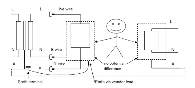
If the earth-neutral exists in the plug of the equipment being supplied, the equipment will not work. There are now no dangerous voltages exposed.
However it is probably safer to leave the equipment with no connection from chassis to earth. Better still once it is obvious that the equipment will not work the fault should be investigated
Monday, August 12, 2013
Auto Sound Systems are an Investment in your Car Make it Great
For those who love tunes and the ability to take them along wherever you may roam, there are some great auto sound systems that allow you to basically plug in your favorite tunes to play as you go. It doesnt really matter which style of MP3 player you use, most of the newer auto sound systems at least have the ability to read and translate the material from these players into great music for you to enjoy on your ride by simply plugging your MP3 player into the car stereo.
 Many of us find that lugging around an MP3 player with all of our favorite tunes (or at least most of them-with up to 40 gigs of hard drive space it might take a while to fill completely) is much easier and more practical than attempting to lug around a huge case of CDs. It is also great for those of us who find ourselves disappointed when we purchase CDs only to find that we really only like one or two songs. Now we can simply download the songs we know and love while avoiding those we are uncertain about or at least waiting until more songs come out before deciding whether or not to purchase the entire collection of songs. Having an auto sound system that allows you to enjoy the convenience of simply plugging in either your MP3 player or a memory card or stick in order to have your favorite songs at your finger tips at all times is fantastic.
I dont know about you, but I am absolutely hooked on audio books. I love to read and find so little free time in which to get my feel of the latest and greatest best seller. Audio books allow me to hear the stories Ive been eagerly awaiting at my convenience and in my SUV as Im making my daily commute or running errands. These books are also a great way to enjoy long car trips. You can even check your local library in order to find an excellent selection.
I typically try to find stories that might interest the children on long car rides as well (such as the Harry Potter books or The Polar Express). This instills a love of reading in them and I dont have to worry about the stray grown up word that some audio books contain. Good auto sound systems not only play great music but also sound wonderful when it comes to the spoken word as well. This is not only true when it comes to books on tape, CD, or MP3 but also talk radio and national news stations as well.
When you begin your search for your next auto sound system make sure you consider all the possible features you may wish to include. You can find sound systems today that include GPS, DVD players, navigational tools, CD players, MP3 players, satellite radio receivers and countless other nifty features. Choose the auto sound system that will suit your needs and interests best and enjoy it for as long as you can. A good sound system is something that will stay with your car, truck, or SUV so it is best to make that particular investment long before you plan to trade your vehicle in on another. At the same time a good auto sound system can be an excellent incentive to hold onto your vehicle a little while longer.
Sunday, August 11, 2013
Power Supply For USB Devices
More and more equipment is sold that runs off internal rechargeable batteries. Although a matching charger is usually supplied in the package, there are also devices that can only be charged via a USB port. That is not surprising in the case of USB MP3 players, which have to ‘dock’ in the PC anyway for some time for the purpose of file transferring. Still, the same ‘feature’ can be a serious disadvantage, for example, on ‘computer-free’ holidays. Sometimes it makes you wonder how simple the solutions to such problems actually turn out to be. After all, if it’s just a supply voltage we’re after, then a USB port is easily imitated.
The circuit shown here is nothing but a 7805 in a dead standard configuration. The innovation, if any, might be USB connector to which the MP3 player can be connected. The 7805 comes in different flavours most devices can supply 1 A, but there are also more advanced variants that achieve up to 1.5 A. Because a USB device is never allowed to draw more than 500 mA from the port it is plugged into, the circuit shown here should be able to supply charging and/or operating current to up to two (or three) USB devices at the same time. The input voltage may be a direct voltage of anything between 7 and 24 volts, so for use at home or abroad a simple wall cube with DC output is sufficient.
Circuit diagram:
Another useful bit to make yourself might be a cable with an inline fuse and a cigarette lighter plug so you can tap into a vehicle supply (note that this may be up to 14.4 V with a running engine). At an output current of 1 A and an input voltage of just 7 V, the 7805 already dissipates 2 watts. Assuming you’re using the most commonly seen version of the 7805, the TO-220 case with its metal tab will have a thermal resistance of about 50 °C/W. Also assuming that the ambient temperature is 20 °C, the 7805’s internal (chip) temperature will be around 120 °C. In most cases, 150 °C is the specified maximum, so ample cooling must be provided especially in a car and with relatively high input voltages.
Continue Read...
The circuit shown here is nothing but a 7805 in a dead standard configuration. The innovation, if any, might be USB connector to which the MP3 player can be connected. The 7805 comes in different flavours most devices can supply 1 A, but there are also more advanced variants that achieve up to 1.5 A. Because a USB device is never allowed to draw more than 500 mA from the port it is plugged into, the circuit shown here should be able to supply charging and/or operating current to up to two (or three) USB devices at the same time. The input voltage may be a direct voltage of anything between 7 and 24 volts, so for use at home or abroad a simple wall cube with DC output is sufficient.
Circuit diagram:
Power Supply Circuit Diagram For USB Devices
Another useful bit to make yourself might be a cable with an inline fuse and a cigarette lighter plug so you can tap into a vehicle supply (note that this may be up to 14.4 V with a running engine). At an output current of 1 A and an input voltage of just 7 V, the 7805 already dissipates 2 watts. Assuming you’re using the most commonly seen version of the 7805, the TO-220 case with its metal tab will have a thermal resistance of about 50 °C/W. Also assuming that the ambient temperature is 20 °C, the 7805’s internal (chip) temperature will be around 120 °C. In most cases, 150 °C is the specified maximum, so ample cooling must be provided especially in a car and with relatively high input voltages.
Friday, August 9, 2013
High Frequency Generator Circuit
This is a design circuit for high frequency waveform generator is very useful in electronic experiment and design. This circuit is generate sine wave oscillation, but actually we can modify the circuit to generate triangle or square wave function. The core of this waveform generator is MAX038. This integrated circuit chip gives complete function to build a waveform generator/function generator. This is the figure of the circuit;

The frequency can be controlled using current. If we disconnect the 20k RIN from REF (pin 1) and connect it to a DAC, then we can control the frequency using microcontroller or digital interface. We can even control the chip using a quartz crystal (PLL) by controlling the current using a phase comparator output that compares the sync output (pin 14 of MAX038) and a reference clock from quartz crystal oscillator. This waveform generator integrated circuit chip is very interesting since it can generate 0.1Hz to 20MHz, very wide operating frequency, as expected for every waveform generator instruments.
Thursday, August 8, 2013
Spike Detector For Oscilloscopes
Dynamic flip-flops ignore pulses at their inputs that are shorter than 40 ns or do not have TTL levels. This means that TTL flip-flops are poorly suited to capturing noise pulses having unknown durations and magnitudes. Anyone who has ever tried to observe very short laser pulses (15–25 ns) is familiar with this problem. By contrast, this circuit can detect impulses with widths less than 8 ns and amplitudes between +100 mV and +5 V. The heart of this circuit is formed by a MAX903, a very fast comparator with internal memory. The IC has separate supply pins for its analogue and digital portions. The analogue portion is powered by a symmetrical ±5-V supply.
This allows the detector to also handle input voltages that are negative relative to ground. The internal memory and output stage operate from a single-ended +5-V supply, so the output signal has proper TTL levels. The MAX903 (IC1) has a special internal memory circuit (latch). The latch either connects the output of the internal comparator directly to the signal output or stores the most recent TTL level and blocks the output of the internal comparator, causing the most recent TTL level appears at the output. This allows short input pulses to be stretched to any desired length. Despite its extremely short switching times, the MAX903 consumes only a modest 18 mW.
 In the quiescent state, the voltage on the Latch input (pin 5) is at 1.75 V. This reference voltage is provided by LED D1, which draws its current via R2. In this state the latch is transparent, and a positive edge at the input appears will appear as a negative transition on the output after a propagation delay of 8 ns (tPD). This only happens if the peak voltage on the input is more positive than ground potential. C1 passes this change in the output voltage level to the Latch input (pin 5). As soon as the voltage on the Latch input drops below 1.4 V, the internal latch switches to the Hold state. In this state, the output is no longer connected to the comparator, and the output remains low for the duration of the latch hold time, regardless of what happens with the input signal.
The latch hold time is determined by the time constant of the C3/R1 network; it has an adjustment range of 100–500 ns. Pulses of this length can be readily observed using practically any oscilloscope. This latch function in this circuit is only triggered if the input signal has a rising edge that crosses the zero-voltage level. The internal latch remains transparent for signals in the range of –5 V to 0 V, so such pulses will not be stretched. If only positive input voltages are anticipated, the negative supply voltage is not necessary and the circuit can be powered from a single +5-V supply. A fast circuit such as this requires a carefully designed circuit board layout. All connections to the IC must be kept very short.
Decoupling capacitors C1 and C2 should preferably be placed immediately adjacent to the supply pins. Pin 3 of the IC can be bent upward and soldered directly to a length of coax or twisted-pair cable (air is still the best insulator). If a coax cable is used, the unbraided screen must not be formed into a long pigtail. It’s better to peel back a short length of the screen, wrap a length of bare wire around it and solder it directly to the ground plane. The supply traces for the analogue and digital portions must be well separated from each other, and each supply must be well decoupled, even if only a single supply voltage (+5 V) is used. The preferred solution is to use two independent voltage regulators.
Continue Read...
This allows the detector to also handle input voltages that are negative relative to ground. The internal memory and output stage operate from a single-ended +5-V supply, so the output signal has proper TTL levels. The MAX903 (IC1) has a special internal memory circuit (latch). The latch either connects the output of the internal comparator directly to the signal output or stores the most recent TTL level and blocks the output of the internal comparator, causing the most recent TTL level appears at the output. This allows short input pulses to be stretched to any desired length. Despite its extremely short switching times, the MAX903 consumes only a modest 18 mW.
In the quiescent state, the voltage on the Latch input (pin 5) is at 1.75 V. This reference voltage is provided by LED D1, which draws its current via R2. In this state the latch is transparent, and a positive edge at the input appears will appear as a negative transition on the output after a propagation delay of 8 ns (tPD). This only happens if the peak voltage on the input is more positive than ground potential. C1 passes this change in the output voltage level to the Latch input (pin 5). As soon as the voltage on the Latch input drops below 1.4 V, the internal latch switches to the Hold state. In this state, the output is no longer connected to the comparator, and the output remains low for the duration of the latch hold time, regardless of what happens with the input signal.The latch hold time is determined by the time constant of the C3/R1 network; it has an adjustment range of 100–500 ns. Pulses of this length can be readily observed using practically any oscilloscope. This latch function in this circuit is only triggered if the input signal has a rising edge that crosses the zero-voltage level. The internal latch remains transparent for signals in the range of –5 V to 0 V, so such pulses will not be stretched. If only positive input voltages are anticipated, the negative supply voltage is not necessary and the circuit can be powered from a single +5-V supply. A fast circuit such as this requires a carefully designed circuit board layout. All connections to the IC must be kept very short.
Decoupling capacitors C1 and C2 should preferably be placed immediately adjacent to the supply pins. Pin 3 of the IC can be bent upward and soldered directly to a length of coax or twisted-pair cable (air is still the best insulator). If a coax cable is used, the unbraided screen must not be formed into a long pigtail. It’s better to peel back a short length of the screen, wrap a length of bare wire around it and solder it directly to the ground plane. The supply traces for the analogue and digital portions must be well separated from each other, and each supply must be well decoupled, even if only a single supply voltage (+5 V) is used. The preferred solution is to use two independent voltage regulators.
Wednesday, August 7, 2013
How to Build a Photodiode current to voltage converter
The Photodiode current-to-voltage converter circuit uses three CA3130 BiMOS op amps in an application sensitive to sub-picoampere input currents. The circuit provides a ground-referenced output voltage proportional to input current flowing through the photo-diode.
Photodiode current-to-voltage converter circuit

Monday, August 5, 2013
Auto Car prevent theft circuit FREQUENCY MODULATION
This FREQUENCY MODULATION radio controlled anti-theft warning signal can be utilised with any vehicle having 6 – to 12-volt DIRECT ELECTRIC CURRENT power grid. The miniskirt VIRAL HAEMORRHAGIC FEVER, FREQUENCY MODULATION sender is climbed on the vehicle at dark, when it is parked in the railcar porch or parking.

The recipient CXA1019, an IC-based FREQUENCY MODULATION wireless mental faculty, which is freely uncommitted on the marketplace at a sensible damage, stays inside. The recipient is tuned up to the relative frequency of the sender. When the vector is on and the signs are experienced by FREQUENCY MODULATION receiving set, no sibilation sound is uncommitted at the recipient turnout. Thus transistor T2 (BC548) not to follow up.
Sunday, August 4, 2013
Citroen Xantia Wiring Diagram Body Electrical System Schematics

1992 Honda Cbr1000f Wiring Diagram And Electrical System.

1986 Fiat Uno Turbo Wiring Diagram And Electrical System Circuit.

Find More Information About Bmw 325e Electrical Wiring Diagram And.

5600 Watt Portable Generator Wiring Diagram Schematic Circuit.

More Information About Ford Taurus Wiring Diagram And Electrical.

Citroen Xantia Wiring Diagram And Body Electrical System Schematics.

Conditioning Electrical Circuit And Wiring Diagram Circuit Schematic.

Rx2 Capella Rottary Wiring Diagram And Electrical System Circuit Here.

1996 Yamaha Tdm850 Wiring Diagram And Electrical System Circuit.

Corolla Wiring Diagram Cable Routing Electrical Schematic Wire Harness.
Friday, August 2, 2013
Simple Up Controlled Negative Voltage Converter Circuit Diagram
This Simple Up-Controlled Negative Voltage Converter Circuit Diagram was used to produce a variable negative voltage for contrast control of an LCD display. A 74F374 generates a square wave that is ac coupled to a rectifier and load. By using the uP clock and data from the processor bus, and properly timed load signal, the dc level generated can be controlled by the uP.
Simple Up-Controlled Negative Voltage Converter Circuit Diagram

Thursday, August 1, 2013
Modular Preamplifier Switching Center
Four high level inputs, Double Bar switching
This module can be a necessary addition to the Modular Preamplifier Control Center when more than two sources need to be connected to the preamplifier chain. Four high level inputs can be selected by means of SW1 and routed to the output. The output of this module must be connected by a suitable cable to one of the two inputs of the Control Center module. In this way, a total of five inputs will be available to the user of this module combination. The Switching Control features also the so called "Double Bar", i.e. the possibility of routing to an external unit, e.g. a recorder (tape or digital) an input signal different from that reproduced at the time by the amplifier.
For example, you can listen in to a CD whereas the signal coming from a radio station through the Tuner is routed to the recorder. This selection is operated by means of SW2. As with the other modules of this series, each electronic board can be fitted into a standard enclosure: Hammond extruded aluminum cases are well suited to host the boards of this preamp. In particular, the cases sized 16 x 10.3 x 5.3 cm or 22 x 10.3 x 5.3 cm have a very good look when stacked. See below an example of the possible arrangement of the front and rear panels of this module.

Modular Preamp Switching Center Circuit Diagram
Parts:R1,R2,R3,R4____100K 1/4W Resistors
R5____________560R 1/4W Resistor
SW1,SW2______2 poles 4 ways Rotary Switches
J1 to J6______RCA audio input sockets
Notes:
- No power supply is necessary for this module
- The circuit diagram shows the Left channel only, so all the parts must be doubled except SW1 and SW2 which are double pole switches, i.e. ready for stereo.
A possible arrangement of the front and rear panels of this Module


Source : http://www.ecircuitslab.com/2011/06/modular-preamplifier-switching-center.html
Subscribe to:
Posts (Atom)