Showing posts with label with. Show all posts
Showing posts with label with. Show all posts
Tuesday, April 30, 2013
Cross Linking With Two Patch Cables
In networks, the supremacy of coax cable is a thing of the past. Nowadays, Ethernet connections are made using UTP cables. The BNC plug has yielded to the 8-way RJ45 plug. Previously, coax cables were daisy-chained from computer to computer and terminated at the two ends using 50-_ resistors, but modern networks use central ‘socket boxes’ (switches and/or hubs) to interconnect everything. The connections between the hubs and the computers are made using patch cables having the same sequence of leads in the RJ45 connectors at each end. For making a direct connection between two computers without using a hub or switch, a ‘crossover cable’ is used.


 Such a cable has the leads cross-linked in order to allow the two computers to directly communicate with each other. If there are problems with the network, it can be handy to be able to directly interconnect twocomputers, or directly connect a computer to a cable or ADSL modem without using a hub or switch. A long crossover cable is not always available, and shoving around computers is not an attractive alternative. Consequently, we can use a dual RJ45 wall outlet box to construct an adapter, which can be used to interconnect the two patch cables coming from the equipment in question. This outlet box must be wired to create a cross-linked connection. This is done by making the following internal connections:


 Such a cable has the leads cross-linked in order to allow the two computers to directly communicate with each other. If there are problems with the network, it can be handy to be able to directly interconnect twocomputers, or directly connect a computer to a cable or ADSL modem without using a hub or switch. A long crossover cable is not always available, and shoving around computers is not an attractive alternative. Consequently, we can use a dual RJ45 wall outlet box to construct an adapter, which can be used to interconnect the two patch cables coming from the equipment in question. This outlet box must be wired to create a cross-linked connection. This is done by making the following internal connections:
- 1 → 3
- 2 → 6
- 3 → 1
- 4 → 4
- 5 → 5
- 6 → 2
- 7 → 7
- 8 → 8

Tuesday, April 9, 2013
BC557 based Flashing Eyes circuit with explanation
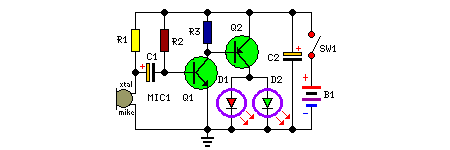
Two-LED-eyes follow the rhythm of music or speech, 3V Battery-operated device suitable for pins or badges
This
circuit was purposely designed as a funny Halloween gadget. It should
be placed to the rear of a badge or pin bearing a typical Halloween
character image, e.g. a pumpkin, skull, black cat, witch, ghost etc.
Two LEDs are fixed in place of the eyes of the character and will shine
more or less brightly following the rhythm of the music or speech
picked-up from surroundings by a small microphone. Two transistors
provide the necessary amplification and drive the LEDs.
Parts:
R1 = 10K
R2 = 1M
R3 = 1K
C1 = 4.7uF-25V
C2 = 47uF-25V
D1 = 2mm LED
D2 = 2mm LED
Q1 = BC547
Q2 = BC557
B1 = 3V Battery
SW1 = SPST Switch
MIC1 = Electret Mic
Notes:
* Any general purpose, small signal transistor can be used for Q1 and
Q2, but please note that R3 could require adjustment, depending on
the gain of Q1. For medium gain transistors, the suggested value should
do the job. High gain transistors will require a lower value for R3,
i.e. about 390 – 470 Ohm. You can substitute R3 with a 1K Trimmer in
order to set precisely the threshold of the circuit.
* Any LED type and color can be used, but small, 2mm diameter, high efficiency LEDs will produce a better effect.
* No limiting resistors are required for D1 and D2 even if this could seem incorrect.
* Stand-by current consumption of the circuit is about 1.5mA.
* Depending on dimensions of your badge, you can choose from a wide variety of battery types:
* 2 x 1.5 V batteries type: AA, AAA, AAAA, button clock-type, photo-camera type & others.
* 2 x 1.4 V mercury batteries, button clock-type.
Sunday, April 7, 2013
10 000x With One Transistor
For a collector follower with emitter resistor, you’ll often find that the gain per stage is no more than 10 to 50 times. The gain increases when the emitter resistor is omitted. Unfortunately, the distortion also increases. With a ubiquitous transistor such as the BC547B, the gain of the transistor is roughly equal to 40 times the collector current (Ic), provided the collector current is less than a few milliamps. This value is in theory equal to the expression q/KT, where q is the charge of the electron, K is Boltzmann’s constant and T is the temperature in Kelvin.
For simplicity, and assuming room temperature, we round this value to 40. For a single stage amplifier circuit with grounded emitter it holds that the gain Uout /Uin (for AC voltage) is in theory equal to SRc. As we observed before, the slope S is about 40Ic. From this follows that the gain is approximately equal to 40I cRc. What does this mean? In the first instance this leads to a very practical rule of thumb: that gain of a grounded emitter circuit amounts to 40·I c·Rc, which is equal to 40 times the voltage across the collector resistor.
If Ub is, for example, equal to 12 V and the collector is set to 5V, then we know, irrespective of the values of the resistors that the gain will be about 40R(12–5) = 280. Notable is the fact that in this way the gain can be very high in theory, by selecting a high power supply voltage. Such a voltage could be obtained from an isolating transformer from the mains. An isolating transformer can be made by connecting the secondaries of two transformers together, which results in a galvanically isolated mains voltage.
Circuit diagram:
 10,000x With One Transistor Circuit diagram
That means, that with a mains voltage of 240 Veff there will be about 340 V DC after rectification and filtering. If in the amplifier circuit the power supply voltage is now 340 V and the collector voltage is 2 V, then the gain is in theory equal to 40 x (340–2). This is more than 13,500 times! However, there are a few drawbacks in practice. This is related to the output characteristic of the transistor. In practice, it turns out that the transistor does actually have an output resistor between collector and emitter.
This output resistance exists as a transistor parameter and is called ‘hoe’. In normal designs this parameter is of no consequence because it has no noticeable effect if the collector resistor is not large. When powering the amplifier from 340 V and setting the collector current to 1 mA, the collector resistor will have a value of 338 k. Whether the ‘hoe’-parameter has any influence depends in the type of transistor. We also note that with such high gains, the base-collector capacitance in particular will start to play a role.
As a consequence the input frequency may not be too high. For a higher bandwidth we will have to use a transistor with small Cbc, such as a BF494 or perhaps even an SHF transistor such as a BFR91A. We will have to adjust the value of the base resistor to the new hfe. The author has carried out measurements with a BC547B at a power supply voltage of 30 V. A value of 2 V was chosen for the collector voltage. Measurements confirm the rule of thumb. The gain was more than 1,000 times and the effects of ‘hoe’ and the base-collector capacitance were not noticeable because of the now much smaller collector resistor.
Author: Gert Baars Copyright: Elektor Electronics
Saturday, April 6, 2013
Running LED with 4017
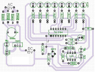
Running LED with 4017 complete with PCB layout. The series of 8 LED current is the basis for creating an 8-point LED. Slightly different from the running LED with IC 4017 (decade counter), 8 running this led is lit in sequence, but that has been previously flame does not die when the led is lit afterwards. 8 led to death after led to the fire-8. Meanwhile in the running LED (decade counter), the system LED lights like "point", there is only one LED that flashes between the tenth led.

The main component is the IC 74LS164 (SHIFT REGISTER), with its timer is astable multivibrator circuit (using IC NE555).
The series will be more efficient when using a stable power supply (regulator) using IC Regulator 7805. Under this scheme a series of stable power supply 5 volts dc.
Friday, April 5, 2013
Fire alarm with light sensor
Fire alarm can be made with a light sensor (LDR) as in the article with the title of Fire Alarm with this LDR sensor. Principles of fire detection Fire Alarm with LDR sensor is to detect the presence of smoke through the LDR. LDR in the series Fire Alarm does not stand alone in detecting a fire, but the LDR in the pair with the light shining on the LDR.
Hence, in the detected smoke from the fire then the intensity of light received by the LDR LDR decreases and eventually trigger an alarm system on a series of Fire Alarm with this LDR sensor. Part 2 that in the series of Fire Alarm with Sensor LDR are some of the sensors, tone generator, audio power.
Image Series Fire Alarm with Sensor LDR

Function Section of the Fire Alarm with Sensor LDR
Part of LDR and light sensor facing to fire smoke detection
Part trigger using transistors and regulators as a trigger tone generator 7805
Tone generator section with IC UM66
Power audio section uses an audio power IC TDA 2002 which is equipped with voleme control (R3)
Subscribe to:
Posts (Atom)