Friday, December 27, 2013
Park Aid Modification Circuit
Park-Aid Modification Circuit Diagram

R15_____________3K3 1/4W Resistor
R16___________330K 1/4W Resistor
R17___________470K 1/4W Resistor
R18___________150K 1/4W Resistor
C6______________1µF 63V Electrolytic or Polyester Capacitor
D8,D9,D10____1N4148 75V 150mA Diodes
IC4_____________555 Timer IC
BZ1___________Piezo sounder (incorporating 3KHz oscillator)
Wednesday, December 25, 2013
Simple Cmos Motorcycle Alarm Circuit Diagram
Cmos Motorcycle Alarm Schematic Diagram

Veroboard Layout

Tuesday, December 24, 2013
3 Channels Mini Mixer
Simple and cheap mixer circuit. This circuit supplied using 9V power supply. There is high/low-sensitivity switchable inputs for each input channel.
3 Channels Mini Mixer Circuit diagram :

Part List :
P1,P2,P3_________5K Linear Potentiometers
R1,R11,R15_____180K 1/4W Resistors
R2,R12,R16_______2M2 1/4W Resistors
R3,R13,R17_____750R 1/4W Resistors (See Notes)
R4,R14,R18_______1K 1/4W Resistors
R5______________15K 1/4W Resistor
R6_____________220R 1/4W Resistor
R7_______________1K5 1/4W Resistor
R8_____________820R 1/4W Resistor
R9_____________150R 1/4W Resistor
R10____________100K 1/4W Resistor
C1,C6,C8_________1µF 63V Polyester or Electrolytic Capacitors
C2,C4,C7,C9____100µF 25V Electrolytic Capacitors
C3,C5__________220µF 25V Electrolytic Capacitors
Q1,Q4,Q5______BC550C 45V 100mA Low noise High gain NPN Transistors
Q2____________BC547 45V 100mA General purpose NPN Transistor
Q3____________BC557 45V 100mA General purpose PNP Transistor
J1,J2,J3________3mm or 6mm Mono Jack sockets
SW1,2,3,4______SPST Toggle or Slider Switches
B1_______________9V PP3 Battery
Clip for PP3 Battery
Sunday, December 22, 2013
Simple Positive Regulator Circuit Diagram

Saturday, December 21, 2013
Tracking Dual Output Bipolar Supply Circuit Diagram
Thursday, December 19, 2013
Simple Photomultiplier Supply Circuit Diagram

Wednesday, December 18, 2013
The warehouse needs more room to accommodate more Cell Phone Jammers
Intelligently find nearby gas stations, restaurants, supermarkets and parking lots. In the long-distance travel in the car, no longer have to ask how to get high-speed ahead, out of which the intersection, as long as the marked destination, set the priority to high-speed road, will help you plan out where you want to go the best route. Such as Xinjiang from Beijing to self-driving tour, you can enter Urumqi. The warehouse of Cell Phone Jammers is near the subfactory.
When you deviate from the route has been selected, will prompt you off course, and it will automatically re-plan your route. The current map, there are more than 400 cities in the country a detailed map, a small county-level cities have, as well as the countrys highway network detailed map, as well as tourist zones, mountain maps. Mainly in travel, hiking, picnic, etc., when used to plan routes, indicating position, record tourist track. You can climb a Piedmont, mountain climbing using the previous track. GPS devices have the track record of features, such as Guilin, or you want to self-driving tour of Tibet, you can download someone elses track, then do not ask for directions, directly under the flight path travel. The warehouse of Cell Phone Jammers will be closed at four o’clock.
IE browser produced by Microsoft, a browser, and using free (and Win) bundled manner to the user, that is, as long as you use the Win family of operating systems would certainly have the IE browser, but also because So, IE has occupied the vast majority of personal computer browser share, other non-IE (core) browser such as Netscape NETSCAPE, OPERA and FIREFOX also individual users in general are rare. Is a low-power short-range wireless connectivity technology standard in lieu of that, "Bluetooth" is taken from a unified in the 10th century Danish king, Harald II, (Harald) of the nickname, the "Bluetooth" (Bluetooth). "Bluetooth" technology is the first five world-renowned advocate of computer and communications companies: Ericsson, Ericsson, International Business Machines IBM, Intel, Intel, Nokia Nokia, and Toshiba Toshiba. And in May 1998 set up a "Bluetooth" special interest group (Bluetooth Special Interest Group-SIG), the organization adopted a free transfer to industry of the patented technology strategy to achieve its goal of global harmonization of standards. The worker needs to get the needed Cell Phone Jammers before it is closed.
The goal is to achieve maximum data transfer speed 1Mbps (the effective transmission speed of 721kbps), the maximum transmission distance of 10 meters, the user can not have been allowed to use the 2.4GHz ISM (industrial, scientific, medical) band, set up in its 79 channel bandwidth of 1MHz, with a frequency of 1,600 times per second switching, hobbing (hobbing) mode technology to achieve spread spectrum radio transceiver. This is the origin and characteristics of Bluetooth technology. Bluetooth technology to communicate with the equipment, determine the frequency roll into gear mode "caller" and its communication opponent, "by taking sides." Caller before they take the same time by the parties and seven communication. Therefore, the caller can be taken together with the seven parties were famous for the 8 devices to connect Piconet (sawtooth network) subnet. Piconet taken by the parties within the same time as the subject to take more than two parties Piconet. In July 1999, announced the official Bluetooth specification BluetoothVersion 1.0. Comply with the specifications of cell phones and laptop computers will be listed in late 1999 or early 2000. Bluetooth technology products make claims that the companies are growing, the current Bluetooth standards bodies "BluetoothSIG (Special Interest mix)" members of the enterprises has increased to 800 or more.
Monday, December 16, 2013
Simple Positive And Negative Voltage Power Supply Circuit Diagram

Source Simple Positive And Negative Voltage Power Supply Circuit Diagram
Wednesday, October 9, 2013
Auto Power Off
 The switch is formed by a p-n-p darlington, T1, which is actuated by push-button switch S1. The very high amplification of the darlington enables it to be kept on fairly long with the aid of a relatively small-value capacitor, C1 (= 100 µF). Resistor R3 limits the charging current of C1 to ensure a long life of S1. Resistors R1 and R2, in conjunction with C1, determine the switch-on time. When this time has elapsed, R1 ensures that T1 is switched off. Since the darlington can handle a UBE of –10 V, a polarity protection diode is not needed.
Tuesday, October 8, 2013
1994 Chevrolet S10 Blazer Wiring Diagram
 |
| 1994 Chevrolet S10 Blazer |
Sunday, October 6, 2013
Battery Discharger Using Discrete Components
The battery discharger published in this website may be improved by adding a Schottky diode (D3). This ensures that a NiCd cell is discharged not to 0.6–0.7 V, but to just under 1 V as recommended by the manufacturers. An additional effect is then that light-emitting diode D2 flashes when the battery connected to the terminals is flat. The circuit in the diagram is based on an astable multivibrator operating at a frequency of about 25 kHz. When transistor T2 conducts, a current flows through inductor L1, whereupon energy is stored in the resulting electromagnetic field. When T2 is cut off, the field collapses, whereupon a counter-emf is produced at a level that exceeds the forward voltage (about 1.6 V) of D2.

A current then flows through the diode so that this lights. Diode D1 prevents the current flowing through R4 and C2. This process is halted only when the battery voltage no longer provides a sufficient base potential for the transistors. In the original circuit, this happened at about 0.65 V. The addition of the forward bias of D3 (about 0.3 V), the final discharge voltage of the battery is raised to 0.9–1.0 V. Additional resistors R5 and R6 ensure that sufficient current flows through D3. When the battery is discharged to the recommended level, it must be removed from the discharger since, in contrast to the original circuit, a small current continues to flow through D3, R2-R3, and R5-R6 until the battery is totally discharged.
The flashing of D2 when the battery is nearing recommended discharge is caused by the increasing internal resistance of the battery lowering the terminal voltage to below the threshold level. If no current flows, the internal resistance is of no consequence since the terminal voltage rises to the threshold voltage by taking some energy from the battery. When the discharge is complete to the recommended level, the LED goes out. It should therefore be noted that the battery is discharged sufficiently when the LED begins to flash.
Saturday, October 5, 2013
2001 Pontiac Grand Prix Wiring Diagram
 |
| 2001 Pontiac Grand Prix Wiring Diagram |
wire, blue wire, black wire, white black, camshaft position sensor, powertrain control module, knock sensor, camshaft position signal, engine speed signal, crankshaft position sensor, ignition control module, timing control, timing signal.
Thursday, October 3, 2013
Full duplex Intercom Circuit
No complex switching required, Simple circuitry, 6-12V supply
This design allows to operate two intercom stations leaving the operator free of using his/her hands in some other occupation, thus avoiding the usual "push-to-talk" operation mode. No complex changeover switching is required: the two units are connected together by means of a thin screened cable. As both microphones and loudspeakers are always in operation, a special circuit is used to avoid that the loudspeaker output can be picked-up by the microphone enclosed in the same box, causing a very undesirable and loud "howl", i.e. the well known "Larsen effect". A "Private" switch allows microphone muting, if required.
Circuit Diagram :
 Full-duplex Intercom Circuit diagram
Parts:
P1_____________22K Log. Potentiometer
R1_____________22K 1/4W Resistor
R2,R3_________100K 1/4W Resistors
R4_____________47K 1/4W Resistor
R5______________2K2 1/4W Resistor (See Notes)
R6______________6K8 1/4W Resistor
R7_____________22K 1/2W Carbon or Cermet Trimmer
R8______________2K7 1/4W Resistor
C1,C6_________100nF 63V Polyester or Ceramic Capacitors
C2,C3__________10µF 63V Electrolytic Capacitors
C4_____________22µF 25V Electrolytic Capacitor
C5_____________22nF 63V Polyester or Ceramic Capacitor
C7____________470µF 25V Electrolytic Capacitor
Q1____________BC547 45V 100mA NPN Transistor
IC1_________TDA7052 Audio power amplifier IC
SW1____________SPST miniature Switch
MIC____________Miniature electret microphone
SPKR___________8 Ohm Loudspeaker
Screened cable (See Text)
Circuit operation:
The circuit uses the TDA7052 audio power amplifier IC, capable of delivering about 1 Watt of output power at a supply voltage comprised in the 6 - 12V range. The unusual feature of this design is the microphone amplifier Q1: its 180° phase-shifted audio output taken at the Collector and its in-phase output taken at the Emitter are mixed by the C3, C4, R7 and R8 network and R7 is trimmed until the two incoming signals almost cancel out. In this way, the loudspeaker will reproduce a very faint copy of the signals picked-up by the microphone.
At the same time, as both Collectors of the two intercom units are tied together, the 180° phase-shifted signal will pass to the audio amplifier of the second unit without attenuation, so it will be loudly reproduced by its loudspeaker. The same operation will occur when speaking into the microphone of the second unit: if R7 will be correctly set, almost no output will be heard from its loudspeaker but a loud and clear reproduction will be heard at the first unit output.
Notes:
- The circuit is shown already doubled in the diagram. The two units can be built into two separate boxes and connected by a thin screened cable having the length desired.
- The cable screen is the negative ground path and the central wire is the signal path.
- The power supply can be a common wall-plug adapter having a voltage output in the 6 - 12V dc range @ about 200mA.
- Enclosing the power supply in the box of one unit, the other unit can be easily fed by using a two-wire screened cable, its second wire becoming the positive dc path.
- To avoid a two-wire screened cable, each unit may have its own separate power supply.
- Please note that R5 is the only part of the circuit that must not be doubled.
- Closing SW1 prevents signal transmission only, not reception.
- To setup the circuit, rotate the volume control (P1) of the first unit near its maximum and speak into the microphone. Adjust Trimmer R7 until your voice becomes almost inaudible when reproduced by the loudspeaker of the same unit.
- Do the same as above with the second unit.
Source : www.redcircuits.com
Wednesday, October 2, 2013
Video Out Coupling
If you want to connect a video signal to several destinations, you need a distribution amplifier to match the 75-ohm video cable. A distribution amplifier terminates the incoming cable in 75 ohms and provides several outputs, each with 75-ohm output impedance. Since this is usually achieved by putting a 75-ohm series resistor in the output lead of each video opamp (current-feedback amplifier), the opamps must be set up for a gain of 2 in order to achieve an insertion gain of 1 (0 dB). The disadvantage of this arrangement is that if the amplifier or its power supply fails, no signal is available at any of the outputs. This can be remedied by using a high input impedance amplifier, which can be tapped into a video line without having to have its own 75-ohm termination resistor.


In order to eliminate hum interference and voltage differences between the cable screen and the circuit earth, the circuit exploits the common-mode rejection of the opamp. This can be optimized with resistor RG1. With the indicated LT1396 video opamp, more than 40 dB of common-mode rejection can be achieved. The signal bandwidth of the circuit can be optimized using the trimpots. It reaches to more than 10 MHz, which is quite acceptable for video signals. Thanks to the high-impedance connection to the video line, the video signal is not affected when the power for the coupled amplifier is switched off. You can learn more about the LT1396 from its data sheet at http://www.linear-tech.com.
Monday, September 30, 2013
Programming The Propeller IC
Parallax, well known for its successful Basic Stamp IC, has recently introduced the Propeller: a new microcontroller with a certain difference. It packs no less than eight 32-bit processors (referred to as COGs in Propeller jargon) into a single package with only 40 pins. That design takes genuine simultaneous multiprocessing possible, and the sophisticated internal structure of the device makes it relatively easy to implement video and signal-processing applications. The Propeller can be programmed in assembly language or the high-level Spin language. The processor and the programming tools were developed entirely in-house by Parallax, with the hardware being designed from scratch starting at the transistor level.
Circuit diagram:

Programming The Propeller IC Circuit Diagram
The basic idea behind that was to avoid becoming involved in all sorts of patent disputes with other manufacturers. The result is astounding, and for software developers it certainly requires a change in mental gears. As is customary with modern microprocessors, the Propeller has a simple serial programming interface. The developer’s toolkit from Parallax has a modern USB port for that purpose, but a reasonably simple alternative (illustrated here) is also possible for anyone who prefers to work with the familiar RS232 port. Don’t forget that the Propeller works with a 3.3-V supply voltage.
Copyright: Elektor Electronics
Sunday, September 29, 2013
Battery Juicer
The circuit features a TBA820M, a cheap audio power amplifier capable of operating from a very low supply voltage. Here it is connected as an astable multivibrator running at a frequency of around 13 kHz. Together with the two diodes and electrolytic capacitor this forms a DC-DC converter which can almost double the voltage from between four and eight series-connected AA-, C- or D-size cells, or from a PP3-style battery. The DC-DC converter is followed by a constant current source which drives the LED. This protects the expensive white LED: the voltages obtained from old batteries can vary considerably.
 With the use of the DC-DC converter and 20 mA constant current source a much greater range of usable input voltages is achieved, particularly helpful at the lower end of the range when old batteries are used. With the constant current source on its own the white LED would not be adequately bright when run from low voltages. An additional feature is the ‘automatic eye’. The LDR detects when the normal room lighting is switched on or when the room is lit by sunlight: its resistance decreases. This reduces the UBE of the transistor below 0.7 V, the BC337 turns off and deactivates the LED.
This prolongs further the life of the old batteries. A further LDR across capacitor C reduces the quiescent current of the circuit to just 4mA (at 4V). Light from the white LED must of course not fall on the LDR, or the current saving function will not work.
Friday, September 27, 2013
Simple Audio Peak Detector

This level is copied to the input of IC1.C via D2 (D1) and due to the inverting action of IC1.C, LED D3 will light. Network R3-C1 provides some delay to enable very short audio peaks to be reliably indicated. Initially turn the wiper of P1 to the +12 V extreme — LED D3 should remain out. Then apply ‘line’ level audio to K1 and K3, preferably music with lots of peaks (for example, drum ‘n bass). Carefully adjust P1 until the peaks in the music are indicated by D3. The circuit has double RCA connectors for the left and right channels to obviate the use of those rare and expensive audio splitter (‘Y’) cables.
Thursday, September 26, 2013
Isolated 1 Hz Clock Circuit
One of the author’s physics projects required an accurate 1-Hz (seconds) clock signal. Unfortunately, precision 10-MHz quartz crystals are expensive, while another problem was found in the inability of most common or garden 40xx CMOS logic chips to work at such a high frequency. However, a typical CMOS counter like the 4017 has such a high input resistance that its clock input has ‘radio’ properties.
Circuit diagram :
 Isolated 1-Hz Clock Circuit Diagram
The effect is exploited here to convert the stray magnetic field picked up from a mains transformer into a clock signal. Here, the signal is induced in a short piece of wire (approx. 5 cm) connected to the clock input of a CD4017 decade counter for division by 10. The resulting 5-Hz signal is then divided by 5 by a second 4017 (IC2) to give an output of 1 Hz. LED D1 flashes to indicate the presence of a sufficiently strong magnetic field. The pickup wire should be placed close to the mains transformer, without compromising electrical safety. Always use the greatest distance at which a clock signal is reliably generated. For 1-Hz output from 60-Hz power systems, use output 6 of IC2 (pin 5).
Tuesday, September 24, 2013
Cat and Dog Repeller
Naturally, it would be nice to avoid startling the entire neighborhood with this alarm signal. Here we can take advantage of the fact that dogs and cats have a significantly better sense of hearing than people. Not only are their ears more sensitive, they can also perceive significantly higher frequencies. With people, the upper limit is around 18 kHz, but dogs and cats can hear frequencies in excess of 20 kHz. We can take advantage of this by building a siren that emits a frequency just above 20 kHz. This will scare off dogs and cats, but people will simply not hear it.
All we need for this is an oscillator with an amplifier stage and a tweeter that can reproduce such high frequencies, such as a piezoelectric tweeter. The schematic diagram shows how easily this can be implemented. The power supply for the entire circuit is formed by the components up to and including C2. The 230-V leads are connected in parallel with the motion-sensor lamp. C1 and R1 provide capacitive coupling to reduce the 230 V to an acceptable voltage. A DC voltage of approximately 9.1 V is generated from this voltage using a bridge rectifier and D1, filtered and buffered by C2. The oscillator is built around R3, C3 and IC1a.
 The frequency of this oscillator is rather dependent on the specific characteristics of IC1, so the values shown here should be regarded as guidelines. If the oscillator frequency is too high, it can be reduced by increasing the value of R3 and/or C3. If the frequency is too low (which means that the siren tone it is audible), the value of R3 and/or C3 should be increased. The square-wave signal from the oscillator is applied to the input of an H bridge composed of several Schmitt triggers in combination with the final output stages (T1–T4). This approach causes the peak-to-peak value of the square wave signal to be twice the supply voltage.
As a result, a respectable 18 V is obtained across the piezoelectric tweeter, which is sufficient to produce a quite loud whistle tone. When building the circuit, you should bear in mind that it is directly powered from 230 V and not electrically isolated from the mains network. It is thus necessary to avoid contact with all of the components when the circuit is in use. In practice, this means that the circuit must be fitted into a well-insulated, waterproof box. If you want to test the circuit, it is a good idea to first discharge C1 using a resistor, since it can hold a dangerous charge. You must also ensure that components F1, C1, R1 and B1 all have a mutual insulation separation of at least 6 mm!
Monday, September 23, 2013
Intelligent Presence Simulator


Resistors
R1 = 1k 500mW
R2 = 4k7
R3 = 560R
R4,R6 = 10k
R5 = 7k5
R 7 = LDR
R8 = 470k to 1 M
P1 = 470k potentiometer
Capacitors
C1 = 470µF 25V
C2 = 10µF 25V
C3 = 1nF5
C4 = 10nF
Semiconductors
D1,D2 = 1N4004
D3 = diode zener 4V7 400 mW
LED1 = LED, red
D4 = 1N4148
T1 = BC547
IC1 = PIC12C508, programmed, see Downloads
Miscellaneous
RE1 = relay, 10A contact
S1 = 1-pole 3-way rotary switch
F1 = fuse 100 mA
TR1 = Mains transformer 2x9 V, 1.2 -3 VA
4 PCB terminal blocks, 5 mm lead pitch
5 solder pins
Downloads:
The PCB layout can be downloaded free from our website www.elektor.com; file # 080231-1.
The source code and .hex files for this project are available free on www.elektor.com; file # 080231-11.zip.
Sunday, September 22, 2013
Digital Isolation up to 100 Mbits

Digital Isolation up to 100 Mbits Circuit Diagram
Friday, September 20, 2013

Wednesday, September 11, 2013
Simple VHF FM Aircraft Receiver

VHF FM Aircraft Receiver is a supererogation receiver developed for listening to FM transmitters but also tunes the aircraft band and the top portion of the FM broadcast band. Receives both AM and FM (107mHz to 135 MHz). You can use this receiver with the any FM transmitter. The receiver is amazingly simple using only one transistor for the receiver section and one IC for the audio section. This circuit is a self-quenching regenerative RF receiver also known as a super regenerative receiver. A superregenerative receiver performs two basic functions.
Tuesday, September 10, 2013
AM Radio built around LM555


Wednesday, September 4, 2013
Designing a Light Detection
Introducing the Light Sensor
LDR resistance changes with changes in light intensity hit it. In the dark, the LDR resistant is about 10 Mohm and the sunniness of 1 kohm or less. LDR is made from semiconductor materials such as cadmium sulfide. With this material, the light energy that falls cause more load is released or the electric current increased payload. That is, the resistance of the material decreases.
LDR is used to convert light energy into electrical energy. Automatic switches and burglar alarms are a few examples of tools that use the LDR. Because the response to light enough slow, LDR is not used in situations where the light intensity changed drastically.
Characteristics of LDR:
1. At the time not given light, LDR has a very high resistance could reach 10 Mohms
2. But when given a light, the barriers will come down drastically so that the voltage and current can pass through the LDR.
So how do we use the characteristics of the LDR to construct a light detector circuit?
Surely this LDR will be combined with other components. Here is an example circuit with LDR and other components.

V+ = (RLDR / R1 + RLDR ) 5V
V- = (P1 / R2 + P1) 5V
For example we want to turn on lights automatically when dusk and the lights off automatically when the early morning. Here we can set the reference voltage to be compared with the input voltage of the LDR, we can set these voltages to match the surrounding light intensity.
Monday, September 2, 2013
SD2 Smoke Detector
SD2 Smoke Detector Circuit diagram

Because the SD2 CMOS Photo-Electric Smoke Detector IC is designed for use in low power, battery operated, consumer applications it needs a 9 volts DC power supply (or a 9 volts battery ).
Sunday, September 1, 2013
Metal Detector Based on the TDA0161
Metal Detector Circuit diagram

This detector electronic circuit operates over a wide range input voltage of 4 -35 volts . If you want you can use other values for the Cx capacitor and for L1 inductor ( changing this value will affect the frequency oscillation and the detection range ) .
Friday, August 30, 2013
Simple Tiny Door Guard
Tiny Door Guard Circuit diagram:

Magnet can be a small sized one that is to be fixed in the door using double sided adhesive tape. Fix the circuit board in the door frame. Fix Reed switch in the door frame, very close to the door. So that, when the door is closed, the magnet will pull the contacts of the reed switch to break supply to the IC. When the door opens, contacts of the reed switch make contact and IC gets power to give alarm.
Thursday, August 15, 2013
High Voltage Regulator Circuit Diagram

Wednesday, August 14, 2013
Safety Isolating Transformer
The purpose of this module is to set safety standards for safety isolating transformers in technical areas and workshops.
The safety isolating transformers covered by this Guidance Note will be various types and will be found:
• as free standing units in workshops
• built in to workshop bench supplies and marked as ‘isolated supply’
• in Radio and TV Studios
• in use with Performers’ equipment in studios
1.1. Safety Isolating Transformers - Principles of operation
A safety isolating transformer is where the input voltage and output voltage are identical, rather than at Separated Extra-Low Voltage (SELV 50V rms maximum), which is strictly the definition in BS 3535. Additionally BS 3535 would exclude the use of domestic socket outlets on the output.
The primary and secondary windings are isolated to Class ll standards by either an earthed electrolytic screen or by being constructed with separate windings on the core. This gives adequate protection from electric shock when working on equipment supplied by such a transformer should either of the supply terminals inside the equipment be touched, as the voltages on the terminals are no longer referred to earth and mains. This is true even if the incoming mains earth is carried through to the equipment chassis.
When such a transformer supplies equipment which normally has a live chassis, a two-wire cable and no internal transformer (e.g. a TV receiver), the hazardous voltage is removed from the chassis as it is floated with respect to mains earth. Touching both terminals at the same time will still result in an electric shock. The problem of using this arrangement during a maintenance operation is that the use of an oscilloscope would not be possible as there would be no earth reference for the probe and the measurement. If the chassis were now grounded by an earth clip to the incoming earth, test equipment such as an oscilloscope could now safely be used and also be correctly referenced.
Commercially produced free-standing/portable safety isolating transformers normally have a BS1363 socket outlet with the earth pin connected to the incoming circuit protective conductor. This does not give maximum protection as will be shown in Appendix 1, and transformers designed/manufactured to BBC Specification were constructed to give an increased degree of protection against a neutral/earth reversal on the equipment. The BBC transformers (UN11/13), which are no longer manufactured, removed the output earth connection from the socket and provided a separate earthed terminal post for connection of an earth lead directly to the chassis of the equipment, to ensure that it was earthed.
As the BBC manufactured unit was no longer available a specification for a suitable unit was written as follows:
A safety isolating transformer is a 240V:240V all-insulated portable Class ll isolating transformer complying with BS3535: Part 1: 1990 or EN 60742:1989 with the following variations:
• the output socket should be an unswitched single socket to BS 1363, with a non conducting casing
• the earth pin of the output socket is to be isolated from the incoming protective conductor to Class ll requirements
• the incoming protective conductor from the supply will be carried through to a green insulated binding post incorporating a 4mm socket to be mounted adjacent to the output socket
2. H&S Legislation
The Electricity at Work Regulations 1989 specifically deal with electrical “systems” in Regulation 4:
(1) All systems shall at all times be of such construction as to prevent, so far as is reasonably practicable, danger.
(2) As may be necessary to prevent danger, all systems shall be maintained so as to prevent, so far as is reasonably practicable, such danger.
(3) Every work activity, including operation, use and maintenance of a system and work near a system, shall be carried out in such a manner as not to give rise, so far as is reasonably practicable, to danger.
(4) Any equipment provided under these Regulations for the purpose of protecting persons at work on or near electrical equipment shall be suitable for the use for which it is provided, be maintained in a condition suitable for that use, and be properly used.
There is no specific need stated in the Regulations which refers to safety isolating transformers.
3. Hazards and risks
The main hazard associated with electrical equipment is electric shock where a fault condition exists and the first line of protection has also failed, or when working with exposed
mains during maintenance. During maintenance the shock would be by direct contact and there are specific precautions to be taken (as specified in EGN12). The use of safety isolating transformers in specific situations where equipment has a live chassis or where a performer’s own electrical equipment is being used can minimise the risk.
4. Electric Shock Protection
An electric shock is only dangerous when the current is greater than about 10mA. Above this level the risk of electrocution is related to the charge, which is dependent on the duration and size of the current flow. A low current for a long time can be as dangerous as a high current for a short time. The voltage is not important except for causing the current passing through the body. Voltages of over 50V normally cause an involuntary action, which will throw off the body, but in some circumstances the body may become ‘locked on’ to the supply. Currents of over 50mA can cause unconsciousness and if prolonged may lead to death.
The current passing through the body depends on the voltage, contact area, moisture level and the body resistance all of which can vary considerably. Under dry conditions the body resistance may be 1500 ohms but can fall to 200 ohms; with a 230V mains supply, this would give currents of about 150mA and 1.2 amps respectively. Such currents could easily cause electrocution, as a normal fuse or circuit breaker would not be expected to break and disconnect the supply. Methods of protection include the use of an RCD or a safety isolating transformer.
5. Selection, use and maintenance of Safety Isolating Transformers
So far as they relate to matters within their control and as is necessary to prevent injury arising, managers must ensure that :
5.1. Selection of safety isolating transformers
5.1.1. Safety isolating transformers are chosen according to their intended conditions and purpose of use
5.1.1.1. Guidance on choice of transformer.
Any transformer should have adequate power rating for the equipment it is to supply. A unit capable of 13 amps (3kW) is probably best, subject to inrush current problems, but the physical size may be a limiting factor in the choice. The BBC transformer unit is rated at 250W (1.1amps) continuous duty, the BBH GU500 at 500W (2.2amps) continuous. If the unit is installed as a bench socket it must be clearly labelled with its maximum load capability.
5.1.1.2. Portable safety Isolating Transformers
Some BBC manufactured units may still be available and should be used subject to passing the Class ll tests. There will be other units from BBH, Farnell or RS that have been suitably modified (Radio Engineering Report R89/68 and R90/2) and they may be also be used subject to satisfactory testing.
5.1.1.3. Installed safety isolating transformers
Installed transformers may be provided on benches in workshops.
These must meet the Class ll requirement. A suitable transformer by RS Components is the TIM300 RS part 278-7103 with the secondary windings in series to give 230V at 1.3A.
5.1.2. A bench-top isolated supply is separated from other outlets providing normal mains, is clearly labelled and has a separate labelled earth terminal
5.1.2.1. Guidance for labelling socket outlets
The label should read :‘Isolated output, earth-free’ ‘earth socket not connected’ ’maximum load……’
5.2. Use of safety isolating transformers
The following requirements define the use of safety isolating transformers:
• a suitable safety isolating transformer is used whenever the risk assessment identifies the need
• a visual inspection is carried out of all safety isolating transformers before use to check there are no obvious signs of damage
• a separate safety isolating transformer is used for each item of equipment
5.2.1.1. Guidance on the use of a safety isolating transformer
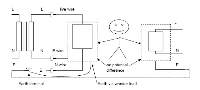
A safety isolating transformer protects against contact with one mains terminal but will not protect against contact with both terminals. If the safety Isolating transformer is in floating mode (not reference to ground), then, as soon as one terminal on the secondary side is touched the other terminal is no longer floating and becomes live and a hazard. For this reason, the chassis of the unit under test should be directly connected to the earth terminal of the transformer i.e. the incoming mains earth, as this is the part most likely to be touched, this ensures that it is at a safe potential.
If the equipment has a live chassis, and depending upon circumstances, you should work using a safety isolating transformer in either of the two following ways:
a) equipment under test remains floating - this is satisfactory provided that only alignment (e.g. potentiometers being adjusted) or voltage measurement (with a digital voltmeter) is being carried out. If you need to take measurements where the measuring device is referred to earth, such as an oscilloscope, then the results will not be satisfactory and an alternative method should be used. If you have to remain in floating mode then the oscilloscope needs to floated on a separate safety isolating transformer.
b) chassis of the equipment under test is connected to mains earth, usually from an earth terminal on the safety isolating transformer (on a BBC Type UN11/13 safety isolating transformer where available) or one provided for the purpose. The chassis is then safe to touch but all other voltages are referred to earth and may be hazardous.
5.2.1.2. Safety isolating transformer or residual current device?
An RCD can be used with high current equipment and more than one piece of equipment can be fed from any one RCD. As soon as a safety isolating transformer is used however, the
protection from an RCD ceases to the secondary windings of the transformer, the cables and equipment connected to the secondary windings.
High current equipment can be accommodated without the bulk and weight of a suitable high power safety isolating transformer.
In most cases the RCD offers greater protection than a safety isolating transformer. This may only be determined by a risk assessment. However neither an RCD nor an isolating transformer should be relied upon to make it safe to work with equipment, other precautions should be taken - see EGN 10 and EGN 3 for more information.
All safety isolating transformers are suitably maintained, and where appropriate, tested by a competent person.
5.3.1.1. Guidance for maintenance of safety isolating transformers.
The maintenance regime for safety isolating transformers require :
• visual inspection - to check plug for damage, the fuse within the plug and transformer is correctly rated, for damage to the mains lead and damage to insulated cases.
• class II insulation test - between input and output L and N terminals. Additionally carry out the test between input earth and the earth pin of the output socket on a BBC type transformer.
• earth continuity test - between the input earth connector and the output earth connector, including any earth binding post.
Up to date records should be kept which demonstrate the maintenance carried out to ensure that the safety isolating transformers are being maintained in a safe condition.
6. Special cases- Performing Band electrical and musical equipment
When bands bring electrical equipment into studios the normal practice has been to supply their equipment from a safety isolating transformer to prevent electrical shock from unknown hazards. More recently it has been the practice to supply from an RCD. However it is known that bands often remove the earth from the mains plug to prevent ‘hum loops’. This is a dangerous practice and if there are hum loops present it is the signal cable earth/screen which should be disconnected at one end only. HSE GS50 gives guidance on this and states that the ‘removal of the protective earth connection is the most common cause of entertainers receiving shocks, some of which have been fatal’. See EGN3.
If a separate safety isolating transformer is used to supply each item of equipment then it may not be necessary to carry out a PAT test as each item is protected by isolation and this method of working may then give the best protection. This will almost certainly mean that a fairly large number of transformers will be required.
The use of a safety isolating transformer remains the recommended practice, as an isolating transformer will prevent the shock whereas an RCD will only reduce the severity of any shock.
Reasons for additional protection given by use of the suggested type transformer
Off the shelf safety isolating transformer.

Improved safety with new method.
If the earth-neutral exists in the plug of the equipment being supplied, the equipment will not work. There are now no dangerous voltages exposed.
However it is probably safer to leave the equipment with no connection from chassis to earth. Better still once it is obvious that the equipment will not work the fault should be investigated
Monday, August 12, 2013
Auto Sound Systems are an Investment in your Car Make it Great
 Many of us find that lugging around an MP3 player with all of our favorite tunes (or at least most of them-with up to 40 gigs of hard drive space it might take a while to fill completely) is much easier and more practical than attempting to lug around a huge case of CDs. It is also great for those of us who find ourselves disappointed when we purchase CDs only to find that we really only like one or two songs. Now we can simply download the songs we know and love while avoiding those we are uncertain about or at least waiting until more songs come out before deciding whether or not to purchase the entire collection of songs. Having an auto sound system that allows you to enjoy the convenience of simply plugging in either your MP3 player or a memory card or stick in order to have your favorite songs at your finger tips at all times is fantastic.
Sunday, August 11, 2013
Power Supply For USB Devices
The circuit shown here is nothing but a 7805 in a dead standard configuration. The innovation, if any, might be USB connector to which the MP3 player can be connected. The 7805 comes in different flavours most devices can supply 1 A, but there are also more advanced variants that achieve up to 1.5 A. Because a USB device is never allowed to draw more than 500 mA from the port it is plugged into, the circuit shown here should be able to supply charging and/or operating current to up to two (or three) USB devices at the same time. The input voltage may be a direct voltage of anything between 7 and 24 volts, so for use at home or abroad a simple wall cube with DC output is sufficient.
Circuit diagram:

Another useful bit to make yourself might be a cable with an inline fuse and a cigarette lighter plug so you can tap into a vehicle supply (note that this may be up to 14.4 V with a running engine). At an output current of 1 A and an input voltage of just 7 V, the 7805 already dissipates 2 watts. Assuming you’re using the most commonly seen version of the 7805, the TO-220 case with its metal tab will have a thermal resistance of about 50 °C/W. Also assuming that the ambient temperature is 20 °C, the 7805’s internal (chip) temperature will be around 120 °C. In most cases, 150 °C is the specified maximum, so ample cooling must be provided especially in a car and with relatively high input voltages.
Friday, August 9, 2013
High Frequency Generator Circuit
