Sunday, September 22, 2013
Digital Isolation up to 100 Mbits
When it is necessary to send a digital signal between two electrically isolated circuits you would normally choose an optoisolator or some form of transformer coupling. Neither of these solutions is ideal; optocouplers run out of steam beyond about 10 MHz and transformers do not have a good low frequency (in the region of Hertz) response.
The company NVE Corporation (www.nve.com) produces a range of coupler devices using an innovative ‘IsoLoop’ technology allowing data rates up to 110 Mbaud. The example shown here uses the IL715 type coupler providing four TTL or CMOS compatible channels with a data rate of 100 Mbit/s. Inputs and outputs are compatible with 3.3 V or 5 V systems. The maximum isolation voltage is 2.5 kV and the device can cope with input transients up to 20 kV/µs.
Circuit diagram:

Digital Isolation up to 100 Mbits Circuit Diagram
The company produce many other configurations including bidirectional versions that would be suitable for RS485 interfacing. The IsoLoop coupler is based on relatively new GMR (GiantMagnetoResistive) technology. The input signal produces a current in a planar coil. This current generates a magnetic field that produces a change in resistance of the GMR material.
This material is isolated from the planar coil by a thin film high voltage insulating layer. The change in resistance is amplified and fed to a comparator to produce a digital output signal. Differences in the ground potential of either the input or output stage will not produce any current flow in the planar coil and therefore no magnetic field changes to affect the GMR material. Altogether the circuit provides a good electrical isolation between input and output and also protects against input signal transients (EMV).
Author: Gregor Kleine - Copyright: Elektor July-August 2004

Friday, September 20, 2013

Wednesday, September 11, 2013
Simple VHF FM Aircraft Receiver

VHF FM Aircraft Receiver is a supererogation receiver developed for listening to FM transmitters but also tunes the aircraft band and the top portion of the FM broadcast band. Receives both AM and FM (107mHz to 135 MHz). You can use this receiver with the any FM transmitter. The receiver is amazingly simple using only one transistor for the receiver section and one IC for the audio section. This circuit is a self-quenching regenerative RF receiver also known as a super regenerative receiver. A superregenerative receiver performs two basic functions.
First it feeds back a portion of the received signal from it’s output in phase to its input; and second a super audible quenching oscillator drives the amplifier through the point of oscillation and maximum sensitivity and then quenches the oscillation repeatedly. This keeps the feedback from driving the circuit into self-oscillation and allows the signal to be regenerated over and over again. In this version of the circuit, both functions are performed by the circuitry associated with Q1. The rest of the circuit, shown to the right of L3 in the schematic, comprise the audio amplification circuit and are centered on the LM386 Audio Amp IC. In this configuration the LM386 is set at a gain of 200 and feeds it’s output to a standard 1/8-inch diameter stereo phone jack. The audio can then be heard by plugging any standard stereo headset into the jack.
Tuesday, September 10, 2013
AM Radio built around LM555
AM Radio built around LM555 Circuit


Continue Read...
AM radio built around 555 timer chip. The only active device (silicon, germanium, or otherwise) is the LM555. The tuning is accomplished with an inductor and a capacitor, and the LM555 acts as an AM demodulator and class-D power amplifier to drive the speaker. You may be wondering how all this is accomplished with a 555. Here’s how the circuit works: The AM radio signal is tuned by inductor L, which is 300 turns of wire on a 1/2 inch diameter cardboard tube made out of a paper roll, along with the 100pF variable capacitor. One end of the parallel configuration of L and C connects to an antenna (surprisingly long!) and the other end connects to a ground wire which is tied to the AC outlet ground (old books tell you to ground it to a water pipe).
So far this is exactly like an AM crystal radio. The 555 timer is configured as a pulse width modulator in a non-traditional configuration. If I used the standard approach and connected the input to the CV pin, the low impedance of the pin would prevent the circuit from receiving any radio signals. I had to invert the circuit and tie both high impedance analog pins, Threshold and Trigger to the radio signal input. This is the reason why the CMOS version of the 555 timer performs much better than the standard bipolar, which has higher input bias current.
Wednesday, September 4, 2013
Designing a Light Detection
In designing a circuit that can detect light, the most important component is the light sensor. One of the light sensor that we often encounter is LDR (Light Dependent Resistor).
Introducing the Light Sensor
LDR resistance changes with changes in light intensity hit it. In the dark, the LDR resistant is about 10 Mohm and the sunniness of 1 kohm or less. LDR is made from semiconductor materials such as cadmium sulfide. With this material, the light energy that falls cause more load is released or the electric current increased payload. That is, the resistance of the material decreases.
LDR is used to convert light energy into electrical energy. Automatic switches and burglar alarms are a few examples of tools that use the LDR. Because the response to light enough slow, LDR is not used in situations where the light intensity changed drastically.
Characteristics of LDR:
1. At the time not given light, LDR has a very high resistance could reach 10 Mohms
2. But when given a light, the barriers will come down drastically so that the voltage and current can pass through the LDR.
So how do we use the characteristics of the LDR to construct a light detector circuit?
Surely this LDR will be combined with other components. Here is an example circuit with LDR and other components.

From the picture above, we can set (varying) the value of R1, R2 and potentiometer P1.
V+ = (RLDR / R1 + RLDR ) 5V
V- = (P1 / R2 + P1) 5V
For example we want to turn on lights automatically when dusk and the lights off automatically when the early morning. Here we can set the reference voltage to be compared with the input voltage of the LDR, we can set these voltages to match the surrounding light intensity.
Monday, September 2, 2013
SD2 Smoke Detector
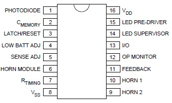
This smoke detector circuit diagram is based on the SD2 CMOS Photo-Electric Smoke Detector Integrated Circuit manufactured by Supertex INC and include almost all needed components to build a very simple and high efficiency smoke detector project .As you can see , this smoke detector circuit diagram is very simple an require few external components .
SD2 Smoke Detector Circuit diagram

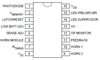 The LED predriver output pulses an external transistor which in turn, switches on the infrared light emitting diode at a very low duty cycle. The desired IR LED pulse period is determined by the value of the externai timing resistor. The Smoke Sensitivity is adjustable through a trimmer resistor which varies the IR LED puise width. The light sensing element is a silicon photovoltaic cell which is held at near zero bias to minimize leakage currents. The circuit can detect signals as low as 1 mV and generate an alarm. The IR LED pulse repetition rate increases when smoke is detected. The IR diode can be RCA Type SG 1010A or Spectronics Type SE 5455-4 Clairex and the IR Photo detector can be Vactec VTS4085 .
Because the SD2 CMOS Photo-Electric Smoke Detector IC is designed for use in low power, battery operated, consumer applications it needs a 9 volts DC power supply (or a 9 volts battery ).
SD2 Smoke Detector Circuit diagram

Because the SD2 CMOS Photo-Electric Smoke Detector IC is designed for use in low power, battery operated, consumer applications it needs a 9 volts DC power supply (or a 9 volts battery ).
Sunday, September 1, 2013
Metal Detector Based on the TDA0161
These metal detector circuit diagram is based on the TDA0161 monolithic integrated circuit , designed for metallic body detection by detecting the variations in high frequency Eddy current losses. For detecting metals , TDA0161 require an external LC tuned circuit .
Metal Detector Circuit diagram

Output signal is determined by supply current changes. Independent of supply voltage, this current is high or low according to the presence or the absence of a close metallic object. This metal detector circuit use two LEDs , which offer an visual indication of presence or absence at a metals ,around the coil . To adjust the circuit you need to make sure there is no metal near the coil and then set the fine adjustment to a "Mid position". After that you need to adjust the course adjustment to turn on the LED and , adjust the fine adjustment to turn off the LED.
This detector electronic circuit operates over a wide range input voltage of 4 -35 volts . If you want you can use other values for the Cx capacitor and for L1 inductor ( changing this value will affect the frequency oscillation and the detection range ) .
Metal Detector Circuit diagram

This detector electronic circuit operates over a wide range input voltage of 4 -35 volts . If you want you can use other values for the Cx capacitor and for L1 inductor ( changing this value will affect the frequency oscillation and the detection range ) .
Subscribe to:
Posts (Atom)