Showing posts with label supply. Show all posts
Showing posts with label supply. Show all posts
Saturday, December 21, 2013
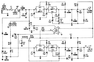
Tracking Dual Output Bipolar Supply Circuit Diagram
This Tracking Dual Output Bipolar Supply Circuit Diagram is useful for a bench supply in the lab. Separate or tracking operation is possible. The regulators should be properly heatsinked. Tl is a 24-Vac wall transformer of suitable current capacity.
Tracking Dual Output Bipolar Supply Circuit Diagram

Thursday, December 19, 2013
Simple Photomultiplier Supply Circuit Diagram
This is a Simple Photomultiplier Supply Circuit Diagram and Cockcroft-Walton voltage multiplier supplies the stepped voltage required for the dynodes of the PMT without the power-wasting voltage- divider resistor string that is traditionally used.
Simple Photomultiplier Supply Circuit Diagram

Monday, December 16, 2013
Simple Positive And Negative Voltage Power Supply Circuit Diagram
This Simple Positive And Negative Voltage Power Supply Circuit Diagram provides a precision voltage source that can be adjusted through zero to positive and negative voltages, which eliminates reversing connections on the power supply. Also, it is possible to get exactly 0 V, without some offset. As to how this circuit works, first consider the -1 V/V to +1 V/V linear gain-control amp (see the figure). A Burr-Brown INA105 difference amp is used in a unity-gain inverting amp configuration.
Positive And Negative Voltage Power Supply Circuit Diagram

A potentiometer is connected between the input and ground. The pot`s slider is connected to the noninverting input of the unity-gain amp; this input is typically connected to ground. With the slider at the bottom of the pot, the circuit is a normal-precision unity-gain inverting amp with a gain of -1.0 V/V ± 0.01% maximum.
With the slider at the top of the pot, the circuit is a normal-precision voltage follower with a gain of ± 1.0 V/V ± 0.001% maximum. With the slider in the center, there`s equal positive and negative gain for a net gain of 0 V/V. The accuracy between the top and the bottom will usually be limited by the accuracy of the pot.
Source Simple Positive And Negative Voltage Power Supply Circuit Diagram
Source Simple Positive And Negative Voltage Power Supply Circuit Diagram
Sunday, August 11, 2013
Power Supply For USB Devices
More and more equipment is sold that runs off internal rechargeable batteries. Although a matching charger is usually supplied in the package, there are also devices that can only be charged via a USB port. That is not surprising in the case of USB MP3 players, which have to ‘dock’ in the PC anyway for some time for the purpose of file transferring. Still, the same ‘feature’ can be a serious disadvantage, for example, on ‘computer-free’ holidays. Sometimes it makes you wonder how simple the solutions to such problems actually turn out to be. After all, if it’s just a supply voltage we’re after, then a USB port is easily imitated.
The circuit shown here is nothing but a 7805 in a dead standard configuration. The innovation, if any, might be USB connector to which the MP3 player can be connected. The 7805 comes in different flavours most devices can supply 1 A, but there are also more advanced variants that achieve up to 1.5 A. Because a USB device is never allowed to draw more than 500 mA from the port it is plugged into, the circuit shown here should be able to supply charging and/or operating current to up to two (or three) USB devices at the same time. The input voltage may be a direct voltage of anything between 7 and 24 volts, so for use at home or abroad a simple wall cube with DC output is sufficient.
Circuit diagram:
Another useful bit to make yourself might be a cable with an inline fuse and a cigarette lighter plug so you can tap into a vehicle supply (note that this may be up to 14.4 V with a running engine). At an output current of 1 A and an input voltage of just 7 V, the 7805 already dissipates 2 watts. Assuming you’re using the most commonly seen version of the 7805, the TO-220 case with its metal tab will have a thermal resistance of about 50 °C/W. Also assuming that the ambient temperature is 20 °C, the 7805’s internal (chip) temperature will be around 120 °C. In most cases, 150 °C is the specified maximum, so ample cooling must be provided especially in a car and with relatively high input voltages.
Continue Read...
The circuit shown here is nothing but a 7805 in a dead standard configuration. The innovation, if any, might be USB connector to which the MP3 player can be connected. The 7805 comes in different flavours most devices can supply 1 A, but there are also more advanced variants that achieve up to 1.5 A. Because a USB device is never allowed to draw more than 500 mA from the port it is plugged into, the circuit shown here should be able to supply charging and/or operating current to up to two (or three) USB devices at the same time. The input voltage may be a direct voltage of anything between 7 and 24 volts, so for use at home or abroad a simple wall cube with DC output is sufficient.
Circuit diagram:

Power Supply Circuit Diagram For USB Devices
Another useful bit to make yourself might be a cable with an inline fuse and a cigarette lighter plug so you can tap into a vehicle supply (note that this may be up to 14.4 V with a running engine). At an output current of 1 A and an input voltage of just 7 V, the 7805 already dissipates 2 watts. Assuming you’re using the most commonly seen version of the 7805, the TO-220 case with its metal tab will have a thermal resistance of about 50 °C/W. Also assuming that the ambient temperature is 20 °C, the 7805’s internal (chip) temperature will be around 120 °C. In most cases, 150 °C is the specified maximum, so ample cooling must be provided especially in a car and with relatively high input voltages.
Friday, April 12, 2013
5 to 15V Regulated Power Supply Rise
Regulated Power Supply


Continue Read...
This project is an ordinary DC regulated power supply that may be a variable DC voltage range from 5V to 15V. It can provide present up to 400mA to power the various circuits in your digital projects. The voltage output is different with the aid of the usage of the potentiometer V.R1. In this circuit, the enter line energy provide is designed for 240V.A.C. If 110VAC enter is used, alter the rankings of the varistor to 150VAC & the transformer ratio to 110V/12V.
Fuse F1 is used as a protection in case theres any short circuit in the circuit. Varistor V1 is hooked up in parallel to the enter of the road voltage to clamp the surge voltage from the road to a cheap level that helps to offer safety to the transformer & other circuitry. One time the voltage degree surge to a excessive level past the flexibility of the varistor to absorb it, fuse F1 or varistor V1 or both will burn. If this circuit failed after a duration of operation, check that the fuse & the varistor are nonetheless in good condition or else exchange them.
Diodes D1, D2, D3 and D4 are used to rectify the 12V.A.C voltage to DC voltage. Electrolytic capacitor E1 is used as a smoothing capacitor to reduce the ripple of the DC voltage. The DC voltage is fed in to the enter of 7805 regulator the place the output DC voltage is got. Changing the value of VR1 will alter the output of the DC voltage. Capacitor C1 is used to filter excessive frequency section from the facility supply.
Tuesday, April 9, 2013
230 V AC To 400 V DC Power Supply Circuit Diagram

Description
A lot of students are who dont know how to convert 230 volt AC to 400 DC. So today I am published 230 V AC to 400 V DC circuit diagram on my blog. Working principle of this circuit diagram is very simple. You already knew the working principle of a bridge rectifier. This circuit is same as bridge rectifier and the working principle is also same. The fuse is used to protect the circuit, if the current is greater than 1 A.
Parts List
| Component No: | Value |
| F1 | 1 A |
| B1 | IN4007 |
| C1 | 470MF/450V |
| V1 | 230 V AC |
Source by : link
Monday, April 8, 2013
Enabling 3 Phase Motor to Operates Using Single Phase Supply
Capacitor have been use for decades to operate 3-phase motors on single-phase power. Two single-phase wires are connected to two of the inputs on a 3 phase motor on this method. Then, the capacitors is connected to one of the single -phase inputs and the third leg of the motor. This is the figure of the circuit;

The voltage is allowed to be displaced in time from its parent voltage by phase shift through the capacitor. Voltage distinct from the 2 single-phase lines is the result. The motor will operate if the capacitors value-it’s ability to process electrical current- is sufficient. 6 times as much current to start as it does to run is required by the motor so a static-capacitor phase converter must have some means of switching a large group of capacitors in and out during motor starting. Below is a typical unit uses a potential-type motor starting relay (pirated from a single-phase motor) to regulate the larger start capacitor, while a smaller (in value) capacitor provides continuous power to run the motor. The potential relay removes the start capacitor from the circuit as the motor speed increase, and the motor operates. [Circuit diagram source: gwm4-3phase.com]
Subscribe to:
Posts (Atom)