Tuesday, April 9, 2013
12V to 220V Converter Circuit
DIY 12V to 220V voltage converter is build with CMOS 4047 that is the
main component of this small voltage converter that transforms a 12V DC into 220V AC.
4047 is used as a astable mutivibrator, at pins 10 and 11 will have a
symmetrical rectangular signal wich is amplified b 2 Darlington
transistors and finally reach the secondary coil of mains transformer (
2x10V / 60VA ).
With
the help of P1 the output frequency can be adjusted between 50Hz to
400Hz. Although this is not part of any professional dc ac converters
it can be used quite effective on some home appliances.
12V to 220V Voltage Converter Circuit Diagram

For more DC to AC voltage converters check the related posts.
Check out the tags for more 12 Volts to 220 Volts converters.

12V Flourescent Lamp Inverter

230 V AC To 400 V DC Power Supply Circuit Diagram

A lot of students are who dont know how to convert 230 volt AC to 400 DC. So today I am published 230 V AC to 400 V DC circuit diagram on my blog. Working principle of this circuit diagram is very simple. You already knew the working principle of a bridge rectifier. This circuit is same as bridge rectifier and the working principle is also same. The fuse is used to protect the circuit, if the current is greater than 1 A.
Parts List
| Component No: | Value |
| F1 | 1 A |
| B1 | IN4007 |
| C1 | 470MF/450V |
| V1 | 230 V AC |
Source by : link
LED Bar Off Indicator
 This results in T3, in conjunction with R5 and the internal reference voltage of IC1, to form a current source that causes a constant current to flow through D11 so that the diode lights. When on of diodes D1–D10 lights, a potential difference ensues across R3, which causes T1 to come on. This results in T2 being switched off so that there is no collector current through T3. Consequently, there is no feedback at the emitter of T3, so that the current through R2 rises appreciably. The current through R2 determines the current through the LEDs in the bar. Therefore, when T3 is enabled, the current through R2, and thus the total current in the circuit, is reduced considerably.
M8031 ding dong circuit diagram
The circuit M8031 has a built-in RC oscillator and digital envelope circuits that make it to require few external components . The sound generated by the M8031 simulate an mechanical ding-dong sound. The M8031 operates from a low input voltage from 1.3 to 3.3 volts requiring low current . The integrated circuit is ideal for door bell application.

Simple Tester For IC 555

Timer IC 555 multipurpose has habit to emerge in so many various wide circuits. Because of this is very useful small components, hence this component becomes very popular in the last few years. Though IC 555 in general hardly relied on, but sometimes happened also error. Circuit designed here will give way of simple and effective to do assaying of damage component. The timer which wish to be tested ( 555), connected as multivibrators is unstable (free running). If nipple SW1 is depressed closed, hence condenser C1 will start loaded [by] through preventive reactor R1 and R2. Soon after strain level at this condenser reach point of timer launch, hence internal of flip-flop will be moved and pin 7 is degraded its the strain to empty C1.
Reset flip-flop when strain C1 reachs threshold level IC. This thing causes boosts pin 7 and impregnation cycle starts again. Output timer (pin3) attributed to a couple of LED. If high output of LED D2 will on and D1 will turn off. On the contrary, when low output of D1 will on and D2 is off. LED will wink if IC in good condition.
For reader having other application and wish to change its (the frequency, hence speed of LED is determined the value by value from R1, R2, and C1. Frequency countable oscillation passed formula:
If R2 far bigger than R1, hence its the frequency can be estimated from formula following:
Value to showed in circuit, oscillation frequency around 0,5 Hz. Test device can be designed considerably compact with soldering all components directly at test collar IC, firstly is attached through aperture at hole surface of box device which will be used. In rotation, all components can be attached at as of slab PCB. Usage of current a minimum and can be supplied from a battery 9V.
BC557 based Flashing Eyes circuit with explanation
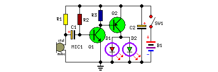
Two-LED-eyes follow the rhythm of music or speech, 3V Battery-operated device suitable for pins or badges
This
circuit was purposely designed as a funny Halloween gadget. It should
be placed to the rear of a badge or pin bearing a typical Halloween
character image, e.g. a pumpkin, skull, black cat, witch, ghost etc.
Two LEDs are fixed in place of the eyes of the character and will shine
more or less brightly following the rhythm of the music or speech
picked-up from surroundings by a small microphone. Two transistors
provide the necessary amplification and drive the LEDs.
Parts:
R1 = 10K
R2 = 1M
R3 = 1K
C1 = 4.7uF-25V
C2 = 47uF-25V
D1 = 2mm LED
D2 = 2mm LED
Q1 = BC547
Q2 = BC557
B1 = 3V Battery
SW1 = SPST Switch
MIC1 = Electret Mic
Notes:
* Any general purpose, small signal transistor can be used for Q1 and
Q2, but please note that R3 could require adjustment, depending on
the gain of Q1. For medium gain transistors, the suggested value should
do the job. High gain transistors will require a lower value for R3,
i.e. about 390 – 470 Ohm. You can substitute R3 with a 1K Trimmer in
order to set precisely the threshold of the circuit.
* Any LED type and color can be used, but small, 2mm diameter, high efficiency LEDs will produce a better effect.
* No limiting resistors are required for D1 and D2 even if this could seem incorrect.
* Stand-by current consumption of the circuit is about 1.5mA.
* Depending on dimensions of your badge, you can choose from a wide variety of battery types:
* 2 x 1.5 V batteries type: AA, AAA, AAAA, button clock-type, photo-camera type & others.
* 2 x 1.4 V mercury batteries, button clock-type.