Swith For diagram

Sunday, April 7, 2013

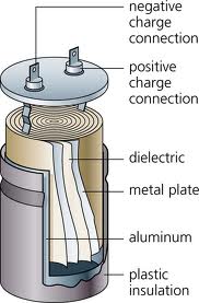
Discharge the large electrolytic capacitor load


If the switching regulator fails to work or fail to start, then it is usually of the electrolytic capacitor is storing charge. There are habits of some engineers dumping electrolyte capacitor
like this using solder. This is actually a poor habit. Because without
them knowing things like this sometimes can lead to broken solder
element.


Why this may happen?


Elco CapacitorsElectrolytic CapacitorNote that the voltage on the electric charge of the electrolyte capacitor is 300V. While working voltage 220v only solder element. If the charge on the electrolytic capacitors are still full and the 220u electrolytic capacitors or more then this electric charge can only damage the solder element.


Another bad habit of throwing of the electrolytic capacitor is to download shortkan legs electrolyte capacitor with a screwdriver. It is no possibility of damaging electrolytic capacitor itself, in which connection leg electrolyte capacitor is no risk in it will burn.


How should the dumping of the electrolytic capacitors?


  • Always provide a resistor with a value of about 30k ~ 50k/2w
  • If the correct power supply to the problem fails to work, then the
    resistor is normally for a while we solder directly on the legs of of
    the electrolytic capacitor. And if the problem is ok, the new resistor is removed.

Posted by netranus at 6:00 PM
Email ThisBlogThis!Share to XShare to FacebookShare to Pinterest
Newer Post Older Post Home

Total Pageviews

Popular Posts

  • Safety Isolating Transformer
    1. Introduction The purpose of this module  is to set safety standards for safety isolating transformers in technical areas and workshops.  ...
  • High And Low Voltage Cut Off Circuit
    This is a design for protection voltage. This circuit is called as high and low voltage cut off. The circuit is using time delay for cut off...
  • How to Make Simple SCR Application Circuits
    SCR is the acronym of Silicon Controlled Rectifier, as the name suggests its a kind of diode or a rectifying agent whose conduction or opera...
  • Simple Delay Timer Circuits Explained
    In many electronic circuit applications a delay of a few seconds or minutes becomes a crucial requirement for ensuring correct operation of ...

Blog Archive

  • ►  2014 (5)
    • ►  January (5)
  • ▼  2013 (128)
    • ►  December (8)
    • ►  October (6)
    • ►  September (13)
    • ►  August (12)
    • ►  July (1)
    • ►  June (1)
    • ►  May (7)
    • ▼  April (80)
      • Cross Linking With Two Patch Cables
      • New Dark Activated Terrace Lamp
      • Stream powers Soldering Iron
      • stream powers low cost Macro Lens
      • Power Indicator for the Water Softener
      • Transistor As a timer circuit
      • Introduction to MatLab Circuit Analysis
      • Clipping Indicator For Audio Amplifiers
      • Automatic Bicycle Light
      • LED Volt Meter Circuit
      • Panasonic 3D FULL HDTV Technology
      • RF Amplifier IC
      • 11 W Stereo or 22 W Mono Power Amp
      • Dark Sensitive Power Switch Circuit Diagram Using LDR
      • 8 Channel LPT Relay Circuit
      • 5 to 15V Regulated Power Supply Rise
      • On Demand WC Fan Using 555
      • Infrared IR Proximity Distance Sensor Circuit
      • Mosfet Battery Charger
      • Amplified Ear Circuit
      • Simple Tan Timer
      • 2Km Fm Transmitter circuit Diagram
      • Long Duration Timer using ATtiny2313
      • Box Kit Home Theaters
      • Hi Fi 25W Power Amplifier Class A
      • Simple Heat Sensor Circuit Diagram
      • Simple 500W 12V to 220V Inverter
      • Valve Sound Converter
      • LCD Module in 4 bit Mode
      • Switch For Switch Free Power Supplies
      • Make an Efficient LED Emergency Light Circuit
      • Basic Components for a Home Theater
      • Trailer Wiring Diagramsjohnson Trailer Salescolfax...
      • 12V to 220V Converter Circuit
      • 12V Flourescent Lamp Inverter
      • 230 V AC To 400 V DC Power Supply Circuit Diagram
      • LED Bar Off Indicator
      • M8031 ding dong circuit diagram
      • Simple Tester For IC 555
      • BC557 based Flashing Eyes circuit with explanation
      • Flugzeuge Archer
      • Auto Sound Systems are more than meets the Eye
      • High And Low Voltage Cut Off Circuit
      • Enabling 3 Phase Motor to Operates Using Single Ph...
      • MINI AUDIO AMPLIFIER ELECTRONIC CIRCUIT DIAGRAM
      • Filter-PreAmp Subwoofer Circuit
      • KA2211 Stereo audio power amplifier
      • Digital Decade Counter Schematic
      • Amplifier circuit for small room
      • 10 000x With One Transistor
      • Discharge the large electrolytic capacitor load
      • Simple Delay Timer Circuits Explained
      • Precision Fahrenheit Temperature Sensors Using LM3...
      • 2000 Ford E 350 electrical Wiring Diagram
      • Traffic Lights Circuit
      • 12 V Bidirectional Motor Control Circuit
      • Fuse Box Toyota 2006 Matrix Under The Dash Diagram
      • Hearing aids circuit
      • Draw Titeconnector Trailer Wiring Harnesseswiring ...
      • Running LED with 4017
      • Electric Wiring Carnone Country Vehicles Located R...
      • Fuse Box Ford 2001 Escape Under Hood Diagram
      • Battery Level Monitor Circuit
      • Guitar Pre Amp Using TL072
      • AC DC Microammeter Circuit
      • The Metal Detector Circuit
      • Fire alarm with light sensor
      • A Discharger for Receiver Battery Packs
      • LCD Module in 4 bit Mode
      • Power On Indicator
      • Predator Controlled Miles Dangerous Combat
      • Anti Theft Security For Car Audios
      • 200W Stereo High Power Amplifier LM3886
      • Sony M8805x Sale L510x Harness Sony Xplod
      • Simple LED Voltmeter
      • Make This Mini Hi Fi Ipod Amplifier Circuit Using ...
      • Precision Temperature Sensor IC LM35 Explained Cel...
      • Electric Trailer Brake Controller Wiring
      • How to Make Simple SCR Application Circuits
      • 4 Minute Shower Timer

About Me

netranus
View my complete profile
Simple theme. Powered by Blogger.