Monday, September 30, 2013
Programming The Propeller IC
Parallax, well known for its successful Basic Stamp IC, has recently introduced the Propeller: a new microcontroller with a certain difference. It packs no less than eight 32-bit processors (referred to as COGs in Propeller jargon) into a single package with only 40 pins. That design takes genuine simultaneous multiprocessing possible, and the sophisticated internal structure of the device makes it relatively easy to implement video and signal-processing applications. The Propeller can be programmed in assembly language or the high-level Spin language. The processor and the programming tools were developed entirely in-house by Parallax, with the hardware being designed from scratch starting at the transistor level.
Circuit diagram:

Programming The Propeller IC Circuit Diagram
The basic idea behind that was to avoid becoming involved in all sorts of patent disputes with other manufacturers. The result is astounding, and for software developers it certainly requires a change in mental gears. As is customary with modern microprocessors, the Propeller has a simple serial programming interface. The developer’s toolkit from Parallax has a modern USB port for that purpose, but a reasonably simple alternative (illustrated here) is also possible for anyone who prefers to work with the familiar RS232 port. Don’t forget that the Propeller works with a 3.3-V supply voltage.
Copyright: Elektor Electronics
Sunday, September 29, 2013
Battery Juicer
The circuit features a TBA820M, a cheap audio power amplifier capable of operating from a very low supply voltage. Here it is connected as an astable multivibrator running at a frequency of around 13 kHz. Together with the two diodes and electrolytic capacitor this forms a DC-DC converter which can almost double the voltage from between four and eight series-connected AA-, C- or D-size cells, or from a PP3-style battery. The DC-DC converter is followed by a constant current source which drives the LED. This protects the expensive white LED: the voltages obtained from old batteries can vary considerably.
 With the use of the DC-DC converter and 20 mA constant current source a much greater range of usable input voltages is achieved, particularly helpful at the lower end of the range when old batteries are used. With the constant current source on its own the white LED would not be adequately bright when run from low voltages. An additional feature is the ‘automatic eye’. The LDR detects when the normal room lighting is switched on or when the room is lit by sunlight: its resistance decreases. This reduces the UBE of the transistor below 0.7 V, the BC337 turns off and deactivates the LED.
This prolongs further the life of the old batteries. A further LDR across capacitor C reduces the quiescent current of the circuit to just 4mA (at 4V). Light from the white LED must of course not fall on the LDR, or the current saving function will not work.
Friday, September 27, 2013
Simple Audio Peak Detector

This level is copied to the input of IC1.C via D2 (D1) and due to the inverting action of IC1.C, LED D3 will light. Network R3-C1 provides some delay to enable very short audio peaks to be reliably indicated. Initially turn the wiper of P1 to the +12 V extreme — LED D3 should remain out. Then apply ‘line’ level audio to K1 and K3, preferably music with lots of peaks (for example, drum ‘n bass). Carefully adjust P1 until the peaks in the music are indicated by D3. The circuit has double RCA connectors for the left and right channels to obviate the use of those rare and expensive audio splitter (‘Y’) cables.
Thursday, September 26, 2013
Isolated 1 Hz Clock Circuit
One of the author’s physics projects required an accurate 1-Hz (seconds) clock signal. Unfortunately, precision 10-MHz quartz crystals are expensive, while another problem was found in the inability of most common or garden 40xx CMOS logic chips to work at such a high frequency. However, a typical CMOS counter like the 4017 has such a high input resistance that its clock input has ‘radio’ properties.
Circuit diagram :
 Isolated 1-Hz Clock Circuit Diagram
The effect is exploited here to convert the stray magnetic field picked up from a mains transformer into a clock signal. Here, the signal is induced in a short piece of wire (approx. 5 cm) connected to the clock input of a CD4017 decade counter for division by 10. The resulting 5-Hz signal is then divided by 5 by a second 4017 (IC2) to give an output of 1 Hz. LED D1 flashes to indicate the presence of a sufficiently strong magnetic field. The pickup wire should be placed close to the mains transformer, without compromising electrical safety. Always use the greatest distance at which a clock signal is reliably generated. For 1-Hz output from 60-Hz power systems, use output 6 of IC2 (pin 5).
Tuesday, September 24, 2013
Cat and Dog Repeller
Naturally, it would be nice to avoid startling the entire neighborhood with this alarm signal. Here we can take advantage of the fact that dogs and cats have a significantly better sense of hearing than people. Not only are their ears more sensitive, they can also perceive significantly higher frequencies. With people, the upper limit is around 18 kHz, but dogs and cats can hear frequencies in excess of 20 kHz. We can take advantage of this by building a siren that emits a frequency just above 20 kHz. This will scare off dogs and cats, but people will simply not hear it.
All we need for this is an oscillator with an amplifier stage and a tweeter that can reproduce such high frequencies, such as a piezoelectric tweeter. The schematic diagram shows how easily this can be implemented. The power supply for the entire circuit is formed by the components up to and including C2. The 230-V leads are connected in parallel with the motion-sensor lamp. C1 and R1 provide capacitive coupling to reduce the 230 V to an acceptable voltage. A DC voltage of approximately 9.1 V is generated from this voltage using a bridge rectifier and D1, filtered and buffered by C2. The oscillator is built around R3, C3 and IC1a.
 The frequency of this oscillator is rather dependent on the specific characteristics of IC1, so the values shown here should be regarded as guidelines. If the oscillator frequency is too high, it can be reduced by increasing the value of R3 and/or C3. If the frequency is too low (which means that the siren tone it is audible), the value of R3 and/or C3 should be increased. The square-wave signal from the oscillator is applied to the input of an H bridge composed of several Schmitt triggers in combination with the final output stages (T1–T4). This approach causes the peak-to-peak value of the square wave signal to be twice the supply voltage.
As a result, a respectable 18 V is obtained across the piezoelectric tweeter, which is sufficient to produce a quite loud whistle tone. When building the circuit, you should bear in mind that it is directly powered from 230 V and not electrically isolated from the mains network. It is thus necessary to avoid contact with all of the components when the circuit is in use. In practice, this means that the circuit must be fitted into a well-insulated, waterproof box. If you want to test the circuit, it is a good idea to first discharge C1 using a resistor, since it can hold a dangerous charge. You must also ensure that components F1, C1, R1 and B1 all have a mutual insulation separation of at least 6 mm!
Monday, September 23, 2013
Intelligent Presence Simulator


Resistors
R1 = 1k 500mW
R2 = 4k7
R3 = 560R
R4,R6 = 10k
R5 = 7k5
R 7 = LDR
R8 = 470k to 1 M
P1 = 470k potentiometer
Capacitors
C1 = 470µF 25V
C2 = 10µF 25V
C3 = 1nF5
C4 = 10nF
Semiconductors
D1,D2 = 1N4004
D3 = diode zener 4V7 400 mW
LED1 = LED, red
D4 = 1N4148
T1 = BC547
IC1 = PIC12C508, programmed, see Downloads
Miscellaneous
RE1 = relay, 10A contact
S1 = 1-pole 3-way rotary switch
F1 = fuse 100 mA
TR1 = Mains transformer 2x9 V, 1.2 -3 VA
4 PCB terminal blocks, 5 mm lead pitch
5 solder pins
Downloads:
The PCB layout can be downloaded free from our website www.elektor.com; file # 080231-1.
The source code and .hex files for this project are available free on www.elektor.com; file # 080231-11.zip.
Sunday, September 22, 2013
Digital Isolation up to 100 Mbits

Digital Isolation up to 100 Mbits Circuit Diagram
Friday, September 20, 2013

Wednesday, September 11, 2013
Simple VHF FM Aircraft Receiver

VHF FM Aircraft Receiver is a supererogation receiver developed for listening to FM transmitters but also tunes the aircraft band and the top portion of the FM broadcast band. Receives both AM and FM (107mHz to 135 MHz). You can use this receiver with the any FM transmitter. The receiver is amazingly simple using only one transistor for the receiver section and one IC for the audio section. This circuit is a self-quenching regenerative RF receiver also known as a super regenerative receiver. A superregenerative receiver performs two basic functions.
Tuesday, September 10, 2013
AM Radio built around LM555


Wednesday, September 4, 2013
Designing a Light Detection
Introducing the Light Sensor
LDR resistance changes with changes in light intensity hit it. In the dark, the LDR resistant is about 10 Mohm and the sunniness of 1 kohm or less. LDR is made from semiconductor materials such as cadmium sulfide. With this material, the light energy that falls cause more load is released or the electric current increased payload. That is, the resistance of the material decreases.
LDR is used to convert light energy into electrical energy. Automatic switches and burglar alarms are a few examples of tools that use the LDR. Because the response to light enough slow, LDR is not used in situations where the light intensity changed drastically.
Characteristics of LDR:
1. At the time not given light, LDR has a very high resistance could reach 10 Mohms
2. But when given a light, the barriers will come down drastically so that the voltage and current can pass through the LDR.
So how do we use the characteristics of the LDR to construct a light detector circuit?
Surely this LDR will be combined with other components. Here is an example circuit with LDR and other components.

V+ = (RLDR / R1 + RLDR ) 5V
V- = (P1 / R2 + P1) 5V
For example we want to turn on lights automatically when dusk and the lights off automatically when the early morning. Here we can set the reference voltage to be compared with the input voltage of the LDR, we can set these voltages to match the surrounding light intensity.
Monday, September 2, 2013
SD2 Smoke Detector
SD2 Smoke Detector Circuit diagram

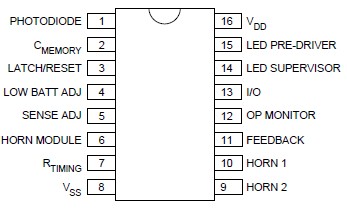
Because the SD2 CMOS Photo-Electric Smoke Detector IC is designed for use in low power, battery operated, consumer applications it needs a 9 volts DC power supply (or a 9 volts battery ).
Sunday, September 1, 2013
Metal Detector Based on the TDA0161
Metal Detector Circuit diagram

This detector electronic circuit operates over a wide range input voltage of 4 -35 volts . If you want you can use other values for the Cx capacitor and for L1 inductor ( changing this value will affect the frequency oscillation and the detection range ) .