Showing posts with label diagram. Show all posts

Thursday, January 9, 2014

Ac to DC Converter Circuit Diagram

This Ac to DC Converter Circuit Diagram includes a PMOS enhancement-mode FET input buffer amplifier, coupled to a classical absolute value circuit which essentially eliminates the effect of the forward voltage drop across diodes D1 and D2. 

Ac to DC Converter Circuit Diagram

Ac to DC Converter Circuit Diagram

Continue Read...

Wednesday, December 25, 2013

Simple Cmos Motorcycle Alarm Circuit Diagram

This Simple Cmos Motorcycle Alarm Circuit Diagram features an intermittent siren output and automatic reset. It can be operated manually using a key-switch or a hidden switch; but it can also be wired to set itself automatically when you turn-off the ignition. By adding external relays you can immobilize the bike - flash the lights etc.

Cmos Motorcycle Alarm Schematic Diagram

Cmos Motorcycle Alarm Circuit Diagram

Notes
Any number of normally-open switches may be used. Fit "tilt" switches that close when the steering is moved or when the bike is lifted off its side-stand or pushed forward off its centre-stand. Use micro-switches to protect removable panels and the lids of panniers etc.

Once activated - the rate at which the siren switches on and off is controlled by R9 & C5. For example - increasing the value of C5 will slow it down - while reducing the value of R9 will make it faster.

While at least one switch remains closed the siren will sound. About thirty seconds after all of the switches have been opened, the alarm will reset. How long it takes to switch off depends on the characteristics of the actual components used. You can adjust the time to suit your requirements by changing the value of R6 and/or C4.

The circuit is designed to use an electronic Siren drawing 300 to 400mA. Its not usually a good idea to use the bikes own Horn because it can be easily located and disconnected. However, if you choose to use the Horn, remember that the alarm relay is too small to carry the necessary current. Connect the coil of a suitably rated relay to the "Siren" output. This can then be used to sound the Horn - flash the lights etc.

The circuit board and switches must be protected from the elements. Dampness or condensation will cause malfunction. Connect the 1-amp in-line fuse AS CLOSE AS POSSIBLE to your power source. This is VERY IMPORTANT. The fuse is there to protect the wiring - not the alarm. Exactly how the system is fitted will depend on the make of your particular machine - so Im unable to provide any further help or advice in this regard.

The quiescent (standby) current of the circuit is virtually zero - so there is no drain on the battery. If you want to operate the alarm manually use a key-switch or a hidden switch connected to the "off/set" terminals. For automatic operation connect a wire from the ignition circuit to the "ignit" terminal. Then every time you turn-off the ignition - the alarm will set itself. Remember that this wire from the ignition switch is not protected by your 1-amp inline fuse. So unless its run is very short - fit the wire with its own 1-amp fuse as close as possible to its source.

When you set the alarm - if one of the switches is closed - the siren will sound. This could cause annoyance late at night. A small modification will allow you to Monitor The State Of The Switches using LEDs. When the LEDs are all off - the switches are all open - and its safe to turn the alarm on.

Veroboard Layout

Cmos Motorcycle Alarm Circuit Diagram


Continue Read...

Sunday, December 22, 2013

Simple Positive Regulator Circuit Diagram

In the Simple Positive Regulator Circuit Diagram, Ql and Q2 are connected in the classic SCR or thyristor configuration. Where higher input voltages or minimum component count are required, the circuit for thyristor boost can be used. 

  Positive Regulator Circuit Diagram

 Positive Regulator Circuit Diagram


The thyristor is running in a linear mode with its cathode as the control terminal and its gate as the output terminal. This is known as the remote base configuration.
Continue Read...

Saturday, December 21, 2013

Tracking Dual Output Bipolar Supply Circuit Diagram

This Tracking Dual Output Bipolar Supply Circuit Diagram is useful for a bench supply in the lab. Separate or tracking operation is possible. The regulators should be properly heatsinked. Tl is a 24-Vac wall transformer of suitable current capacity. 

Tracking Dual Output Bipolar Supply Circuit Diagram 

Tracking Dual Output Bipolar Supply Circuit Diagram

Continue Read...

Thursday, December 19, 2013

Simple Photomultiplier Supply Circuit Diagram

This is a Simple Photomultiplier Supply Circuit Diagram and Cockcroft-Walton voltage multiplier supplies the stepped voltage required for the dynodes of the PMT without the power-wasting voltage- divider resistor string that is traditionally used.

Simple Photomultiplier Supply Circuit Diagram


Continue Read...

Monday, December 16, 2013

Simple Positive And Negative Voltage Power Supply Circuit Diagram

This Simple Positive And Negative Voltage Power Supply Circuit Diagram provides a precision voltage source that can be adjusted through zero to positive and negative voltages, which eliminates reversing connections on the power supply. Also, it is possible to get exactly 0 V, without some offset. As to how this circuit works, first consider the -1 V/V to +1 V/V linear gain-control amp (see the figure). A Burr-Brown INA105 difference amp is used in a unity-gain inverting amp configuration. 

 Positive And Negative Voltage Power Supply Circuit Diagram

Simple Positive And Negative Voltage Power Supply Circuit Diagram


A potentiometer is connected between the input and ground. The pot`s slider is connected to the noninverting input of the unity-gain amp; this input is typically connected to ground. With the slider at the bottom of the pot, the circuit is a normal-precision unity-gain inverting amp with a gain of -1.0 V/V ± 0.01% maximum. 

With the slider at the top of the pot, the circuit is a normal-precision voltage follower with a gain of ± 1.0 V/V ± 0.001% maximum. With the slider in the center, there`s equal positive and negative gain for a net gain of 0 V/V. The accuracy between the top and the bottom will usually be limited by the accuracy of the pot.

Source Simple Positive And Negative Voltage Power Supply Circuit Diagram
Continue Read...

Tuesday, October 8, 2013

1994 Chevrolet S10 Blazer Wiring Diagram

1994 Chevrolet S10 Blazer
(click for full size image)

The Part of 1994 Chevrolet S10 Blazer Wiring Diagram: shunt, fuse block, rear defogger, engine ground, indicator, rear window strut, panel lamps, circuit breaker.
Continue Read...

Saturday, October 5, 2013

2001 Pontiac Grand Prix Wiring Diagram

2001 Pontiac Grand Prix Wiring Diagram
(click for full size image)


The Part of 2001 Pontiac Grand Prix Wiring Diagram: camshaft, fuse block, ignition ctrl module, yellow
wire, blue wire, black wire, white black, camshaft position sensor, powertrain control module, knock sensor, camshaft position signal, engine speed signal, crankshaft position sensor, ignition control module, timing control, timing signal.
Continue Read...

Friday, September 20, 2013

2003 Chevrolet Impala Wiring Diagram

2003 Chevrolet Impala Wiring Diagram

The Part of 2003 Chevrolet Impala Wiring Diagram: message center, instrument panel, coolant temp,
schematics, cooling fan, relay ctrl, serial data, high speed ctrl, black wire, blue wire, junction block, logic
Continue Read...

Thursday, August 15, 2013

High Voltage Regulator Circuit Diagram

The High Voltage Regulator Circuit Diagram delivers 100-V at 100 mA and withstands shorts to ground. Even at 100 V output, the LT317A functions in the normal mode, maintaining 1.2 V between its output and adjustment pin. Under these conditions, the 30-V zener is off and Ql conducts. When an output short occurs, the zener conducts, forcing Q1`s base to 30 V. 

This causes Q1`s emitter to clamp 2 VnEs below Vz. well within the V.w VouT rating of the regulator. Under these conditions, Q1, a high-voltage device, sustains 90 V-VcE at whatever current the transformer specified saturates at 130 mA, while Q1 safely dissipates 12 W. If Q1 and the LT317 A are thermally coupled, the regulator will soon go into thermal shutdown and oscillation will commence. 

This action will continue, protecting the load and the regulator as long as the output remains shorted. The 500-pF capacitor and the 10 0/0.02 11F damper aid transient response and the diodes provide safe discharge paths for the capacitors. 

High Voltage Regulator Circuit Diagram

High Voltage Regulator Circuit Diagram


Continue Read...

Sunday, August 4, 2013

Citroen Xantia Wiring Diagram Body Electrical System Schematics

Electrical Wiring Diagram on 1992 Honda Cbr1000f Wiring Diagram And Electrical System
1992 Honda Cbr1000f Wiring Diagram And Electrical System.


Electrical Wiring Diagram on 1986 Fiat Uno Turbo Wiring Diagram And Electrical System Circuit
1986 Fiat Uno Turbo Wiring Diagram And Electrical System Circuit.


Electrical Wiring Diagram on Find More Information About Bmw 325e Electrical Wiring Diagram And
Find More Information About Bmw 325e Electrical Wiring Diagram And.


Electrical Wiring Diagram on 5600 Watt Portable Generator Wiring Diagram   Schematic   Circuit
5600 Watt Portable Generator Wiring Diagram Schematic Circuit.


Electrical Wiring Diagram on More Information About Ford Taurus Wiring Diagram And Electrical
More Information About Ford Taurus Wiring Diagram And Electrical.


Electrical Wiring Diagram on Citroen Xantia Wiring Diagram And Body Electrical System Schematics
Citroen Xantia Wiring Diagram And Body Electrical System Schematics.


Electrical Wiring Diagram on Conditioning Electrical Circuit And Wiring Diagram   Circuit Schematic
Conditioning Electrical Circuit And Wiring Diagram Circuit Schematic.


Electrical Wiring Diagram on Rx2 Capella Rottary Wiring Diagram And Electrical System Circuit Here
Rx2 Capella Rottary Wiring Diagram And Electrical System Circuit Here.


Electrical Wiring Diagram on 1996 Yamaha Tdm850 Wiring Diagram And Electrical System   Circuit
1996 Yamaha Tdm850 Wiring Diagram And Electrical System Circuit.


Electrical Wiring Diagram on Corolla Wiring Diagram Cable Routing Electrical Schematic Wire Harness
Corolla Wiring Diagram Cable Routing Electrical Schematic Wire Harness.


Continue Read...

Friday, August 2, 2013

Simple Up Controlled Negative Voltage Converter Circuit Diagram

This Simple Up-Controlled Negative Voltage Converter Circuit Diagram was used to produce a variable negative voltage for contrast control of an LCD display. A 74F374 generates a square wave that is ac coupled to a rectifier and load. By using the uP clock and data from the processor bus, and properly timed load signal, the dc level generated can be controlled by the uP. 

Simple Up-Controlled Negative Voltage Converter Circuit Diagram 

Simple Up-Controlled Negative Voltage Converter Circuit Diagram
 
Continue Read...

Tuesday, May 14, 2013

Garden Tractor Wiring Diagram Parts List Manual Parts Book

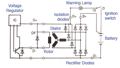
Alternator Wiring Diagram on Testing The Alternator
Testing The Alternator.


Alternator Wiring Diagram on System Circuit And Wiring Diagram  98     02    Circuit Schematic
System Circuit And Wiring Diagram 98 02 Circuit Schematic.


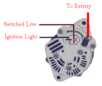
Alternator Wiring Diagram on Jam S Tiger Avon  Wiring A Nippon Denso Alternator
Jam S Tiger Avon Wiring A Nippon Denso Alternator.


Alternator Wiring Diagram on Alternator Wiring Diagram   1978 80 Vehicles
Alternator Wiring Diagram 1978 80 Vehicles.


Alternator Wiring Diagram on Chevy Truck Under Hood Wiring Diagram
Chevy Truck Under Hood Wiring Diagram.


Alternator Wiring Diagram on About Honda Cb400 And Cb450 Wiring Diagram And Schematics Here
About Honda Cb400 And Cb450 Wiring Diagram And Schematics Here.


Alternator Wiring Diagram on Garden Tractor Wiring Diagram Parts List Manual Parts Book
Garden Tractor Wiring Diagram Parts List Manual Parts Book.


Alternator Wiring Diagram on Lexus Sc400 Charging Circuit And Wiring Diagram   Circuit Schematic
Lexus Sc400 Charging Circuit And Wiring Diagram Circuit Schematic.


Alternator Wiring Diagram on Hilux Pickup Power Window Control System Connectors And Wiring Diagram
Hilux Pickup Power Window Control System Connectors And Wiring Diagram.


Alternator Wiring Diagram on 1997 Chevrolet Malibu Wiring Diagram And Electrical System   Circuit
1997 Chevrolet Malibu Wiring Diagram And Electrical System Circuit.
Continue Read...

Friday, April 12, 2013

Dark Sensitive Power Switch Circuit Diagram Using LDR


Description

Circuit showing a Dark Sensitive Power Switch .Here we have used a ldr and a ordinary transistor for making this circuit
.Connect any 230 volt equipment at the load .You need a 9 volt power supply
Components Required

         Resistor

                     10 k , 680 R

          Transistor

                        BC 548

          Diode

                   IN 4007

         Relay

         LDR
Continue Read...

Thursday, April 11, 2013

2Km Fm Transmitter circuit Diagram


This is a powerful transmitter so first of all I would like to tell you not to use this for illeagl things.You can transmitt signals from 2km.Use a matching antenna for this.


Note

# Dont give power without an antenna
# For L1 make 3 turns of 1mm enamelled copper wire on a 10mm diameter plastic former. On the same core make 2 turns of 1 mm enamelled copper wire close to L3 and that will be L2.
# by using R9 the gain can be controlled
# Inductor L3 can be a VK220J type RFC.
# This circuit operates with 9V to 18V ( Dont pass 24V)


Continue Read...

Wednesday, April 10, 2013

Simple Heat Sensor Circuit Diagram

This simple heat sensor circuit could senses heat from various electronics device like computer, amplifier etc. and generate warning alarm. It could senses heat from environment also, but here I mention “electronics device” because it is being using mostly in electronic device to protect them from overheat. 
Simple Heat Sensor Circuit Diagram

Thermistor, 110 Ohms:

Thermistor (110 Ohms)
Fig-2: 110 Ohms Thermistor
As it is a heat sensor circuit, here a thermistor is used as a heat sensor. It is a thermal measurement device and has a variety of usages including temperature sensor/ heat sensor. The thermistor used in this circuit is a NTC (Negative Temperature Coefficient) type thermistor. When temperature increases, its resistance goes decrease. Therefore, NTC thermistor’s resistances are inverse of temperature.

Circuit Description:

You have seen, in this simple circuit diagram of heat sensor, a few number of components is used including a BC548 transistor, a 110 ohms thermistor etc.
  • BC548: BC548 is a TO-92 type NPN transistor, as its alternative you can use 2N2222, BC238, BC548, BC168, BC183 etc. they all have almost same characteristic.
  • 110 Ohms Thermistor: A 110 Ohms thermistor is used to detecting heat. I have told already about it.
  • Buzzer: A buzzer is used with +9V and collector of transistor. When the temperature/ heat exceeds a certain level then it make an alarm.
  • 4.7V Zener diode:  It is used to limit the emitter current of BC548.
  • 9V Battery: A 9V battery is used as a single power source.
  • R1, R2: A 3.3K 1/4w resistor is used as R1 and 100 ohms 1/4w as R2.
  • Switch: Here in this circuit the switch used is a simple SPST switch. You can either use the switch or not, choice is yours. It is not mandatory.

Continue Read...

Tuesday, April 9, 2013

230 V AC To 400 V DC Power Supply Circuit Diagram


Description

               A lot of students are who dont know how to convert 230 volt AC to 400 DC. So today I am published   230 V AC to 400 V DC circuit diagram on my blog. Working principle of this circuit diagram is very simple. You already knew the working principle of a bridge rectifier. This circuit is same as bridge rectifier and the working principle is also same. The fuse is used to protect the circuit, if the current is greater than 1 A.


Parts List

Component No:Value
F11 A
B1IN4007 
C1470MF/450V 
V1230 V AC 


Source by : link
Continue Read...

M8031 ding dong circuit diagram

This electronic circuit diagram is a ding-dong sound effect generator electronic device based on the M8031 circuit designed using CMOS technology.
The circuit M8031 has a built-in RC oscillator and digital envelope circuits that make it to require few external components . The sound generated by the M8031 simulate an mechanical ding-dong sound. The M8031 operates from a low input voltage from 1.3 to 3.3 volts requiring low current . The integrated circuit is ideal for door bell application.


M8031 ding dong electronic circuit diagram
Continue Read...

Monday, April 8, 2013

MINI AUDIO AMPLIFIER ELECTRONIC CIRCUIT DIAGRAM

MINI AUDIO AMPLIFIER ELECTRONIC CIRCUIT DIAGRAM

The 8k2 across the 47u sets the emitter voltage on the BC 547 and this turns it on. The collector is directly connected to the base of a BC 557, called the driver transistor. Both these transistors are now turned on and the output of the BC 557 causes current to flow through the 1k and 470R resistors so that the voltage developed across each resistor turns on the two output transistors. The end result is mid-rail voltage on the join of the two emitters. The two most critical components are 8k2 between the emitter of the first transistor and 0v rail and the 470R resistor.
Continue Read...

Sunday, April 7, 2013

2000 Ford E 350 electrical Wiring Diagram

2000 Ford E-350 electrical Wiring Diagram
(click for full size image)

The Part of 2000 Ford E-350 electrical Wiring Diagram: aero headlamp, power distribution, central
junction box, battery junction box, main light switch, fog switch testing, multifunction switch, daytime running lamp, central junction box, interval wiper/washer, instrument cluster.
Continue Read...